
-
Βιομηχανίες
-
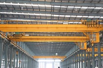
Γενική Βιομηχανία
-
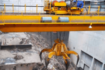
Χειρισμός Απορριμμάτων
-
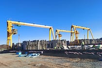
Προκατασκευασμένο
-
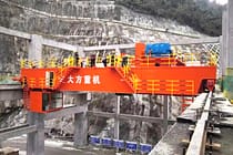
Εξουσία
-
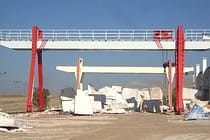
Πέτρα
-
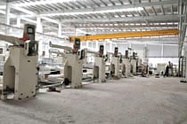
Χαρτοποιία
-
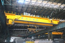
Παραγωγή Μετάλλων
-
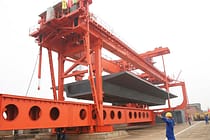
Κατασκευή Γέφυρας
-
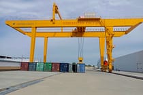
Γερανοί λιμένων: Για χειρισμό εμπορευματοκιβωτίων και χύδην υλικών
-
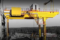
Γερανογέφυρες για τη βιομηχανία πετρελαίου και φυσικού αερίου: Βελτίωση της λειτουργικής αποδοτικότητας
-
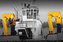
Θαλάσσιοι Γερανοί για Αποδοτική Φόρτωση Φορτίου σε Πλοία
-
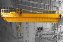
Γερανογέφυρες για την αυτοκινητοβιομηχανία: Αποδοτικές λύσεις αυτοματισμού
-
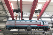
Λύσεις Γερανογεφυρών για Σιδηροδρόμους: Τοποθέτηση Γραμμών, Συντήρηση Τροχαίου Υλικού και Χειρισμός Εμπορευματοκιβωτίων
-
Γερανογέφυρες για τρόφιμα και ποτά: Αξιόπιστες λύσεις για αποτελεσματικό χειρισμό
-
Γερανογέφυρες για Αποδοτική Παραγωγή Τσιμέντου, Γυαλιού, Τούβλων και Προκατασκευασμένου Σκυροδέματος
-
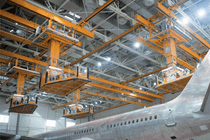
Γερανοί Υπέργειας για την Αεροπορική Βιομηχανία: Συντήρηση και Συναρμολόγηση Αεροσκαφών
-
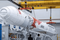
Αεροδιαστημικοί Γερανοί: Ακριβής Ανύψωση για Εκτόξευση και Μεταφορά Πυραύλων
-
-
Προϊόντα
-
Εναέριοι γερανοί
-
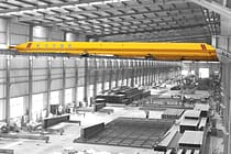
Εναέριοι γερανοί μονής δοκού
-
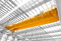
Γερανοί διπλής δοκού
-
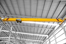
Γερανοί μονής δοκού ευρωπαϊκού τύπου
-
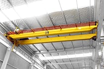
Γερανοί με διπλή δοκό ευρωπαϊκού τύπου
-
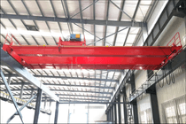
Εναέριοι γερανοί με αντιεκρηκτική προστασία
-
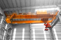
Γερανοί αρπαγής και μαγνητικός
-
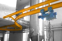
Μονοτροχοί Γερανοί
-
Εναέριοι Γερανοί Χυτηρίου
-
Μονωτικοί γερανοί
-
Γερανοί χαμηλού ύψους
-
Πιάσε τους γερανούς
-

Γερανοί με κουτάλα
-
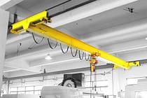
Υπερυψωμένοι γερανοί
-
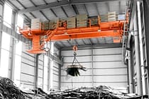
Ηλεκτρομαγνητικοί γερανοί
-
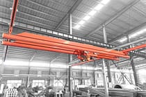
Γερανοί σταθμού εργασίας: Ελαφρύς σχεδιασμός, εύκολη εγκατάσταση και εύκολη λειτουργία
-
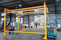
Γερανοί Γέφυρας Ελεύθερου Σταθμού Εργασίας
-
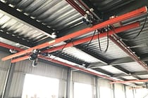
Γερανός γέφυρας τοποθετημένος στην οροφή
-
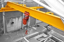
Χειροκίνητες Γερανοί
-
-
Γερανός ατσάλινων σκελετών
-
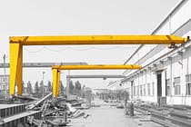
Ημιπυλωτοί Γερανοί
-
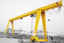
Μονοδοκοί Πυλωτοί Γερανοί
-
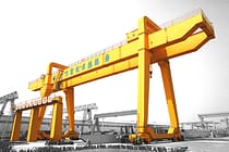
Διδοκοί Πυλωτοί Γερανοί
-
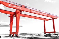
Πυλωτοί Γερανοί Εμπορευματοκιβωτίων
-
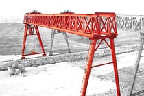
Δικτυωτοί Πυλωτοί Γερανοί
-
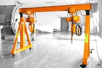
Ρυθμιζόμενοι Πυλωτοί Γερανοί
-
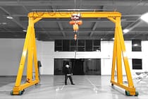
Φορητοί Πυλωτοί Γερανοί
-
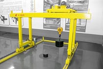
Ευρωπαϊκοί γερανοί γερανογέφυρων
-
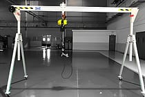
Πυλωτοί Γερανοί Αλουμινίου
-
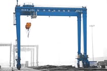
Πυλωτοί Γερανοί Εμπορευματοκιβωτίων με Ελαστικά
-
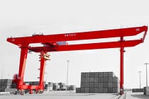
Γερανοί γερανογέφυρων εμπορευματοκιβωτίων που τοποθετούνται σε ράγα
-
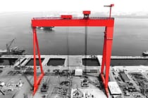
Πυλωτός Γερανός Ναυπηγείου
-
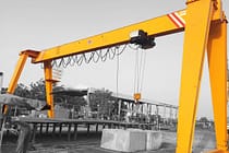
Ευρωπαϊκές γερανογέφυρες μονής δοκού
-
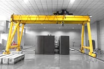
Ευρωπαϊκές γερανογέφυρες διπλής δοκού
-
-
Γερανοί Jib
-
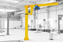
Ελεύθεροι όρθιοι γερανοί φλόκων
-
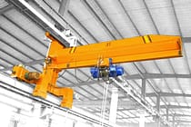
Τοίχοι Ταξιδιωτικοί Γερανοί Jib
-
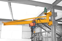
Επιτοίχιοι γερανοί φλόκων
-
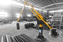
Γερανοί ισορροπίας με φλόκο
-
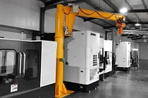
Ηλεκτρικοί γερανοί με κρεμάστρα
-
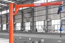
Χειροκίνητοι γερανοί ελεύθερης τοποθέτησης
-
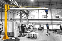
Γερανοί αλουμινίου με φλόκο
-
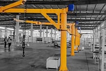
Γερανοί αρθρώσεων
-
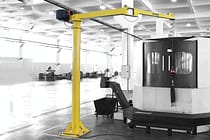
Έξυπνοι γερανοί Jib
-
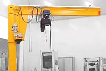
Γερανοί FEM Standard Jib
-
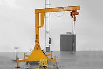
Φορητοί γερανοί Jib
-
- Ειδικοί Γερανοί
- Ηλεκτρικά Ανυψωτικά
- Καρότσια μεταφοράς
-
Εναέριοι γερανοί
-
Ανταλλακτικά γερανού
-
Πιάστε Κουβάδες
-
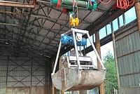
Ηλεκτρικός κάδος από ανοξείδωτο ατσάλι
-
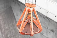
Μηχανικές αρπαγές φλούδας πορτοκαλιού με τέσσερα σχοινιά
-
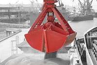
Μηχανικός κάδος αρπαγής με τετρά σχοινιά
-
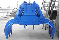
Ηλεκτροϋδραυλικές ορθογώνιες λαβές
-
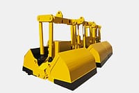
Ηλεκτροϋδραυλικές λαβές Clamshell
-
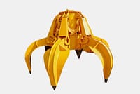
Ηλεκτροϋδραυλικές αρπαγές φλούδας πορτοκαλιού, Υδραυλικές αρπαγές για κάκτους
-
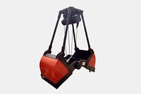
Ηλεκτρική λαβή κινητήρα
-
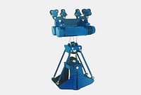
Ηλεκτρικός κάδος αρπάγης μονότροχου με ανυψωτικό μονότροχου
-
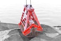
Τηλεχειριστήριο λαβές Clamshell
-
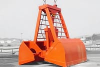
Μηχανικές αρπαγές με δύο σχοινιά
-
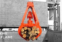
Αρπαγές ξυλείας
-
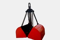
Κάδος αρπαγής με σχοινί
-
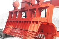
Μηχανήματα Καθαρισμού Σχάρων Απορριμμάτων
-
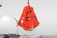
Βυθοκόρηση Αρπαγές
-
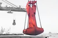
Αρπαγές κοπής
-
- Εξοπλισμός ανύψωσης γερανών
-
Ανταλλακτικά γερανών
-
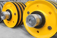
Τροχαλίες γερανών
-
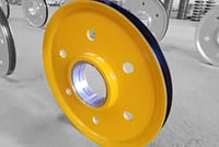
Συρματόσχοινα στάχυα
-
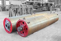
Τύμπανο σχοινιού γερανού
-
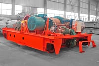
Τρόλεϊ γερανού
-
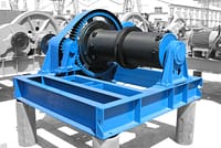
Ηλεκτρικό Βαρούλκο
-
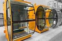
Καμπίνα χειριστή γερανού
-
Φρένα γερανού οροφής
-
Καλώδια εναέριων γερανών
-
Οδηγοί σχοινιού γερανού
-
Αγωγοί εναέριων γερανών και γραμμές παροχής ρεύματος
-
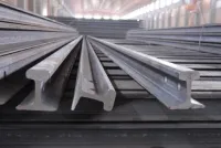
Ράγες γερανού
-
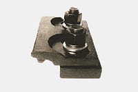
Κλιπ ραγών γερανού
-
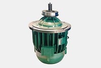
Κινητήρες Γερανών
-
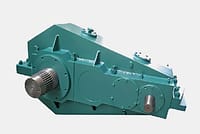
Μειωτήρες Γερανών
-
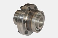
Σύνδεσμοι για εναέριο γερανό
-
- Τροχοί γερανού
-
Πιάστε Κουβάδες
- Εταιρία
- Επικοινωνία

-
Βιομηχανίες
-
Γενική Βιομηχανία
-
Χειρισμός Απορριμμάτων
-
Προκατασκευασμένο
-
Εξουσία
-
Πέτρα
-
Χαρτοποιία
-
Παραγωγή Μετάλλων
-
Κατασκευή Γέφυρας
-
Γερανοί λιμένων: Για χειρισμό εμπορευματοκιβωτίων και χύδην υλικών
-
Γερανογέφυρες για τη βιομηχανία πετρελαίου και φυσικού αερίου: Βελτίωση της λειτουργικής αποδοτικότητας
-
Θαλάσσιοι Γερανοί για Αποδοτική Φόρτωση Φορτίου σε Πλοία
-
Γερανογέφυρες για την αυτοκινητοβιομηχανία: Αποδοτικές λύσεις αυτοματισμού
-
Λύσεις Γερανογεφυρών για Σιδηροδρόμους: Τοποθέτηση Γραμμών, Συντήρηση Τροχαίου Υλικού και Χειρισμός Εμπορευματοκιβωτίων
-
Γερανογέφυρες για τρόφιμα και ποτά: Αξιόπιστες λύσεις για αποτελεσματικό χειρισμό
-
Γερανογέφυρες για Αποδοτική Παραγωγή Τσιμέντου, Γυαλιού, Τούβλων και Προκατασκευασμένου Σκυροδέματος
-
Γερανοί Υπέργειας για την Αεροπορική Βιομηχανία: Συντήρηση και Συναρμολόγηση Αεροσκαφών
-
Αεροδιαστημικοί Γερανοί: Ακριβής Ανύψωση για Εκτόξευση και Μεταφορά Πυραύλων
-
-
Προϊόντα
-
Εναέριοι γερανοί
-
Εναέριοι γερανοί μονής δοκού
-
Γερανοί διπλής δοκού
-
Γερανοί μονής δοκού ευρωπαϊκού τύπου
-
Γερανοί με διπλή δοκό ευρωπαϊκού τύπου
-
Εναέριοι γερανοί με αντιεκρηκτική προστασία
-
Γερανοί αρπαγής και μαγνητικός
-
Μονοτροχοί Γερανοί
-
Εναέριοι Γερανοί Χυτηρίου
-
Μονωτικοί γερανοί
-
Γερανοί χαμηλού ύψους
-
Πιάσε τους γερανούς
-
Γερανοί με κουτάλα
-
Υπερυψωμένοι γερανοί
-
Ηλεκτρομαγνητικοί γερανοί
-
Γερανοί σταθμού εργασίας: Ελαφρύς σχεδιασμός, εύκολη εγκατάσταση και εύκολη λειτουργία
-
Γερανοί Γέφυρας Ελεύθερου Σταθμού Εργασίας
-
Γερανός γέφυρας τοποθετημένος στην οροφή
-
Χειροκίνητες Γερανοί
-
-
Γερανός ατσάλινων σκελετών
-
Ημιπυλωτοί Γερανοί
-
Μονοδοκοί Πυλωτοί Γερανοί
-
Διδοκοί Πυλωτοί Γερανοί
-
Πυλωτοί Γερανοί Εμπορευματοκιβωτίων
-
Δικτυωτοί Πυλωτοί Γερανοί
-
Ρυθμιζόμενοι Πυλωτοί Γερανοί
-
Φορητοί Πυλωτοί Γερανοί
-
Ευρωπαϊκοί γερανοί γερανογέφυρων
-
Πυλωτοί Γερανοί Αλουμινίου
-
Πυλωτοί Γερανοί Εμπορευματοκιβωτίων με Ελαστικά
-
Γερανοί γερανογέφυρων εμπορευματοκιβωτίων που τοποθετούνται σε ράγα
-
Πυλωτός Γερανός Ναυπηγείου
-
Ευρωπαϊκές γερανογέφυρες μονής δοκού
-
Ευρωπαϊκές γερανογέφυρες διπλής δοκού
-
-
Γερανοί Jib
-
Ελεύθεροι όρθιοι γερανοί φλόκων
-
Τοίχοι Ταξιδιωτικοί Γερανοί Jib
-
Επιτοίχιοι γερανοί φλόκων
-
Γερανοί ισορροπίας με φλόκο
-
Ηλεκτρικοί γερανοί με κρεμάστρα
-
Χειροκίνητοι γερανοί ελεύθερης τοποθέτησης
-
Γερανοί αλουμινίου με φλόκο
-
Γερανοί αρθρώσεων
-
Έξυπνοι γερανοί Jib
-
Γερανοί FEM Standard Jib
-
Φορητοί γερανοί Jib
-
- Ειδικοί Γερανοί
- Ηλεκτρικά Ανυψωτικά
- Καρότσια μεταφοράς
-
Εναέριοι γερανοί
-
Ανταλλακτικά γερανού
-
Πιάστε Κουβάδες
-
Ηλεκτρικός κάδος από ανοξείδωτο ατσάλι
-
Μηχανικές αρπαγές φλούδας πορτοκαλιού με τέσσερα σχοινιά
-
Μηχανικός κάδος αρπαγής με τετρά σχοινιά
-
Ηλεκτροϋδραυλικές ορθογώνιες λαβές
-
Ηλεκτροϋδραυλικές λαβές Clamshell
-
Ηλεκτροϋδραυλικές αρπαγές φλούδας πορτοκαλιού, Υδραυλικές αρπαγές για κάκτους
-
Ηλεκτρική λαβή κινητήρα
-
Ηλεκτρικός κάδος αρπάγης μονότροχου με ανυψωτικό μονότροχου
-
Τηλεχειριστήριο λαβές Clamshell
-
Μηχανικές αρπαγές με δύο σχοινιά
-
Αρπαγές ξυλείας
-
Κάδος αρπαγής με σχοινί
-
Μηχανήματα Καθαρισμού Σχάρων Απορριμμάτων
-
Βυθοκόρηση Αρπαγές
-
Αρπαγές κοπής
-
- Εξοπλισμός ανύψωσης γερανών
-
Ανταλλακτικά γερανών
-
Τροχαλίες γερανών
-
Συρματόσχοινα στάχυα
-
Τύμπανο σχοινιού γερανού
-
Τρόλεϊ γερανού
-
Ηλεκτρικό Βαρούλκο
-
Καμπίνα χειριστή γερανού
-
Φρένα γερανού οροφής
-
Καλώδια εναέριων γερανών
-
Οδηγοί σχοινιού γερανού
-
Αγωγοί εναέριων γερανών και γραμμές παροχής ρεύματος
-
Ράγες γερανού
-
Κλιπ ραγών γερανού
-
Κινητήρες Γερανών
-
Μειωτήρες Γερανών
-
Σύνδεσμοι για εναέριο γερανό
-
- Τροχοί γερανού
-
Πιάστε Κουβάδες
- Εταιρία
- Επικοινωνία



Θόρυβος μειωτήρα εναέριας γερανογέφυρας: Ανάλυση εκκεντρικότητας γραναζιών και λύσεις
Πίνακας περιεχομένων
Ο θόρυβος του μειωτήρα εναέριας γερανογέφυρας ενδέχεται να προκληθεί κατά την ανύψωση και τη διαχείριση υλικών σε εργαστήρια, επηρεάζοντας την κανονική λειτουργία του γερανού. Αυτό το άρθρο αναλύει τον ασυνήθιστο θόρυβο από την οπτική γωνία του σφάλματος εκκεντρότητας του ζεύγους γραναζιών. Με βάση τα αποτελέσματα υπολογισμού του δομικού θορύβου από την ανάλυση προσομοίωσης, παρέχει επίσης αντίστοιχες λύσεις ως αναφορά για τη βελτίωση. εναέριος γερανός λειτουργική απόδοση.
Ανάλυση διέγερσης 1 γραναζιού υπό σφάλμα εκκεντρικότητας
Η γερανογέφυρα που αναλύεται σε αυτό το άρθρο είναι ένα μοντέλο LD10 t-28,5 m, εξοπλισμένο με τριφασικό ασύγχρονο κινητήρα 13 kW. Ο μειωτήρας χρησιμοποιεί ένα τετραβάθμιο ελικοειδές κιβώτιο ταχυτήτων παράλληλου άξονα. Όταν λαμβάνεται υπόψη το σφάλμα εκκεντρότητας, η ανάλυση ξεκινά πρώτα από ένα μόνο ζεύγος γραναζιών και το μήκος της γραμμής εμπλοκής του.
1.1 Μοντέλο ζεύγους γραναζιών
Όταν λαμβάνεται υπόψη η εκκεντρότητα του γραναζιού, ως σημείο εκκίνησης χρησιμοποιείται η εκκεντρότητα του κινητήριου και του κινούμενου γραναζιού. Με βάση τον γνωστό αριθμό δοντιών του γραναζιού και την ταχύτητα του κινητήριου γραναζιού, μπορεί να ληφθεί η χαρακτηριστική καμπύλη χρόνου-συχνότητας της ταχύτητας του κινούμενου γραναζιού και να συγκριθεί με το αποτέλεσμα υπό την υπόθεση μηδενικής εκκεντρικότητας. Το μοντέλο ζεύγους εκκεντρικών γραναζιών φαίνεται στο Σχήμα 1.
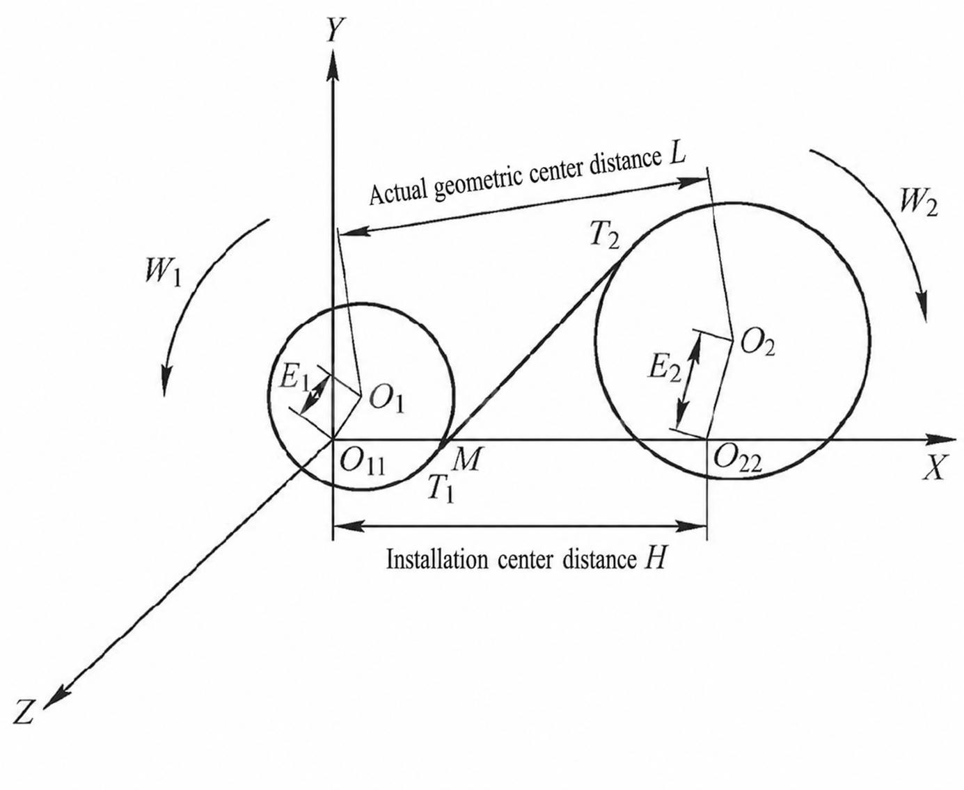
Ο1 και Ο2 είναι τα γεωμετρικά κέντρα του ζεύγους γραναζιών υπό την υπόθεση μηδενικής εκκεντρικότητας. Μετά τις εκκεντρότητες Ε1 και Ε2 συμβαίνουν, τα γεωμετρικά κέντρα των γραναζιών γίνονται Ο11 και Ο22Μπορεί να φανεί ότι, ανεξάρτητα από την τιμή της εκκεντρότητας, η γραμμή εμπλοκής που σχηματίζεται από τη σύνδεση των εφαπτομένων σημείων T1(xT1, yT1) και T2(xT2, yT2) έχει πάντα ένα δυναμικό σημείο τομής M(xM, yM) με τη γραμμή που συνδέει τα γεωμετρικά κέντρα των γραναζιών.
Λαμβάνοντας υπόψη την απόκλιση, η γραμμή εμπλοκής του ζεύγους γραναζιών έχει χρονικά μεταβαλλόμενα χαρακτηριστικά. Η εξίσωσή της μπορεί να εκφραστεί ως:

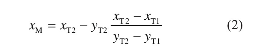
Όταν η αρχή των συντεταγμένων τοποθετείται στο σημείο Ο11, η δυναμική εγκάρσια συντεταγμένη του σημείου Μ μπορεί να εκφραστεί ως:
Η στιγμιαία σχέση μετάδοσης του ζεύγους γραναζιών είναι:
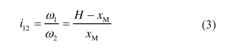
Στον πραγματικό υπολογισμό, το δυναμικό σημείο τομής Μ έχει μια συγκεκριμένη σχέση με τη γραμμή εμπλοκής, τη γωνία μεταξύ της κατεύθυνσης κίνησης και την στιγμιαία ταχύτητα της γραμμής εμπλοκής του γραναζιού. Αφού προσδιοριστεί το εύρος εκκεντρότητας και η γωνιακή ταχύτητα εισόδου, μπορούν να χρησιμοποιηθούν οι τύποι (1) έως (3) για να υπολογιστεί η γωνιακή ταχύτητα του κινούμενου γραναζιού και να υπολογιστεί περαιτέρω η δυναμική διέγερση του ζεύγους γραναζιών υπό σφάλμα εκκεντρότητας.
Στην πραγματική κατασκευή, οι εκκεντρότητες Ε1 και Ε2 μπορεί να ληφθεί περίπου ως το ίδιο. Με εκκεντρότητα ελικοειδούς ζεύγους γραναζιών 20 μm κάτω από τον γνωστό βαθμό ακρίβειας, η υπολογισμένη χαρακτηριστική καμπύλη χρόνου-συχνότητας του κινούμενου γραναζιού φαίνεται στο Σχήμα 2.
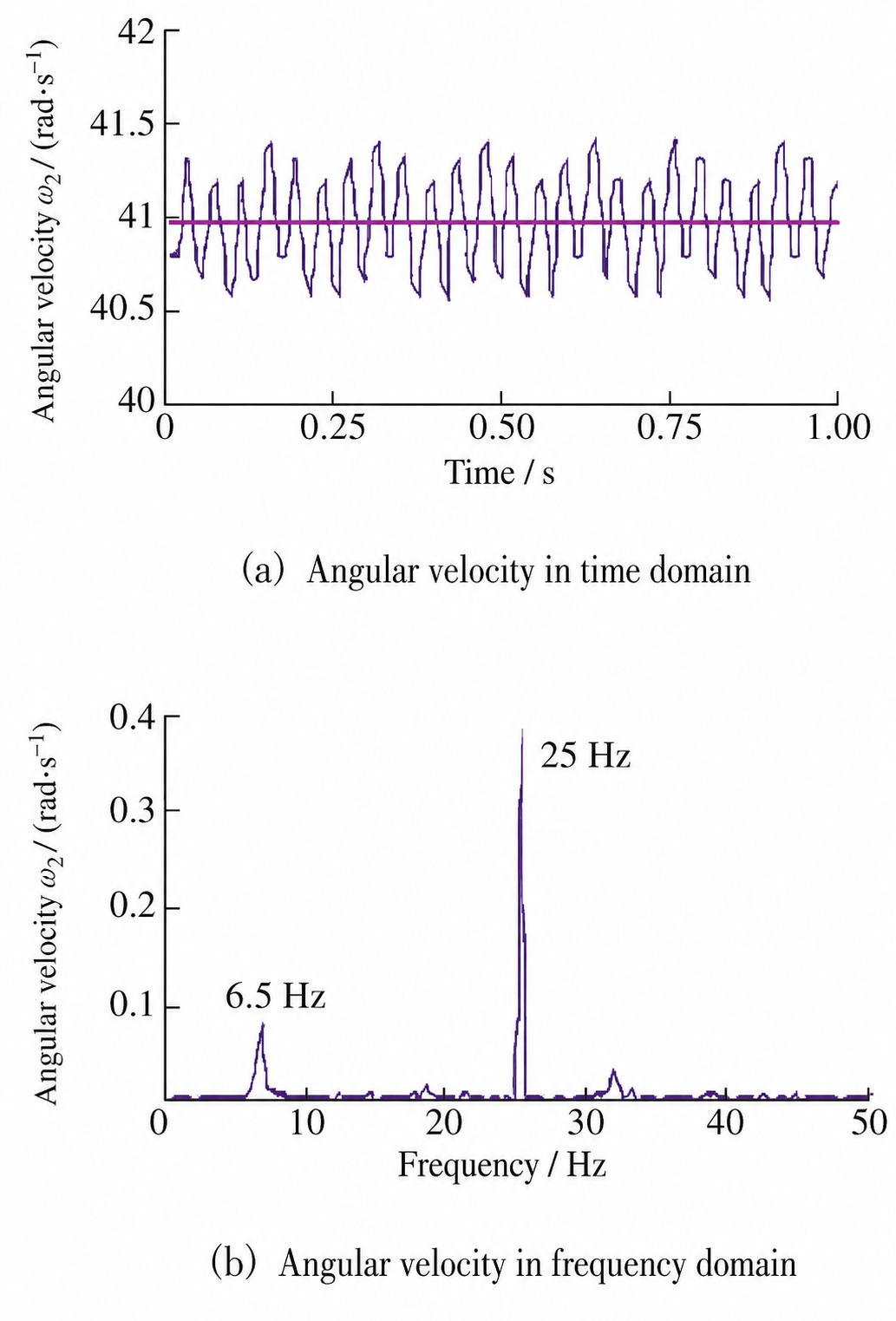
Όταν δεν υποτίθεται σφάλμα εκκεντρικότητας, η γωνιακή ταχύτητα του κινούμενου γραναζιού αναπαρίσταται από την ροζ ευθεία γραμμή στο Σχήμα 2α. Όταν υπάρχει σφάλμα εκκεντρικότητας, η γωνιακή ταχύτητα του κινούμενου γραναζιού παρουσιάζει εμφανή και κανονική διακύμανση, συγκεντρωμένη στην περιοχή των 40,5-41,5 rad/s. Το αποτέλεσμα στο πεδίο συχνότητας μετά τον μετασχηματισμό Fourier αντικατοπτρίζει τη συχνότητα περιστροφής του άξονα εισόδου των 25 Hz και τη συχνότητα περιστροφής εξόδου του κινούμενου γραναζιού των 6,5 Hz. Αυτό υποδεικνύει ότι η διακύμανση εκκεντρικότητας του ζεύγους γραναζιών εισόδου-βαθμίδας μπορεί να συνεχίσει να μεταφέρεται μέσω του συστήματος γραναζιών και να ακτινοβολεί προς το εξωτερικό του κιβωτίου ταχυτήτων.
2 Αριθμητικός Υπολογισμός της Διέγερσης των Γραναζιών στον Θόρυβο του Μειωτή Γερανογέφυρας
2.1 Διαφορική Εξίσωση Δόνησης
Η διαφορική εξίσωση κραδασμών του συστήματος γραναζιών σε έναν μειωτήρα γερανού αποτελεί σημαντική βάση για τη μελέτη των δυναμικών χαρακτηριστικών του. Μειώνοντας την τάξη και υπολογίζοντας τη δυναμική δύναμη εμπλοκής του γραναζιού, μπορούν να προσομοιωθούν αριθμητικά χαρακτηριστικά κραδασμών, όπως η ένταση των κραδασμών και ο δομικός θόρυβος. Η απαιτούμενη διαφορική εξίσωση δεύτερης τάξης είναι:

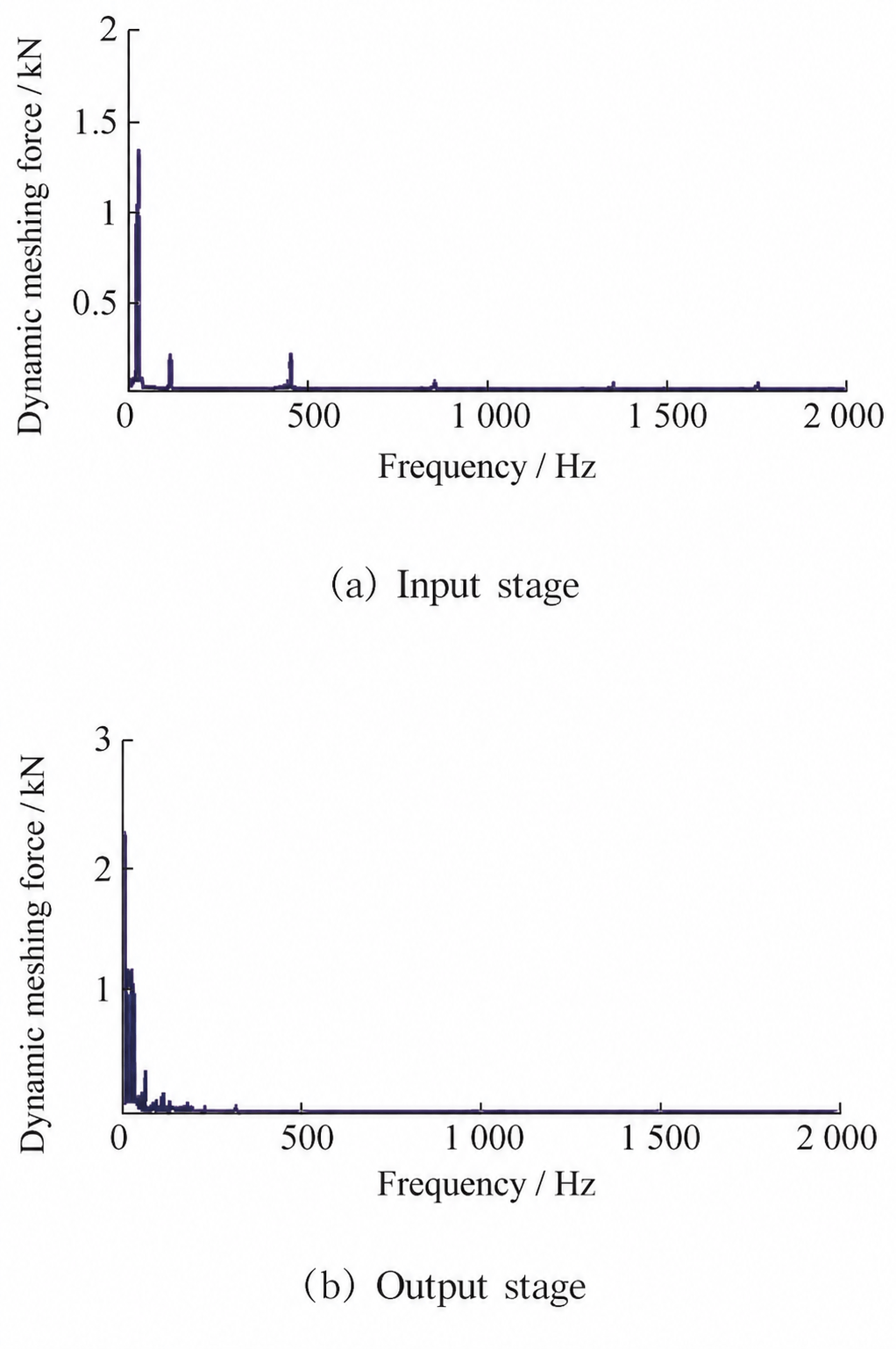
Η χρονική εξίσωση δυναμικής συντεταγμένης Μ αντικαθίσταται σε θ, και η αρχή της μείωσης τάξης Runge-Kutta χρησιμοποιείται για την επίλυση της δυναμικής δύναμης εμπλοκής του ζεύγους γραναζιών υψηλής ταχύτητας. Το Σχήμα 3 δείχνει τα αποτελέσματα υπολογισμού της δύναμης εμπλοκής για το στάδιο εισόδου και το τελικό στάδιο εξόδου.
2.2 Αποτελέσματα Ανάλυσης Κραδασμών
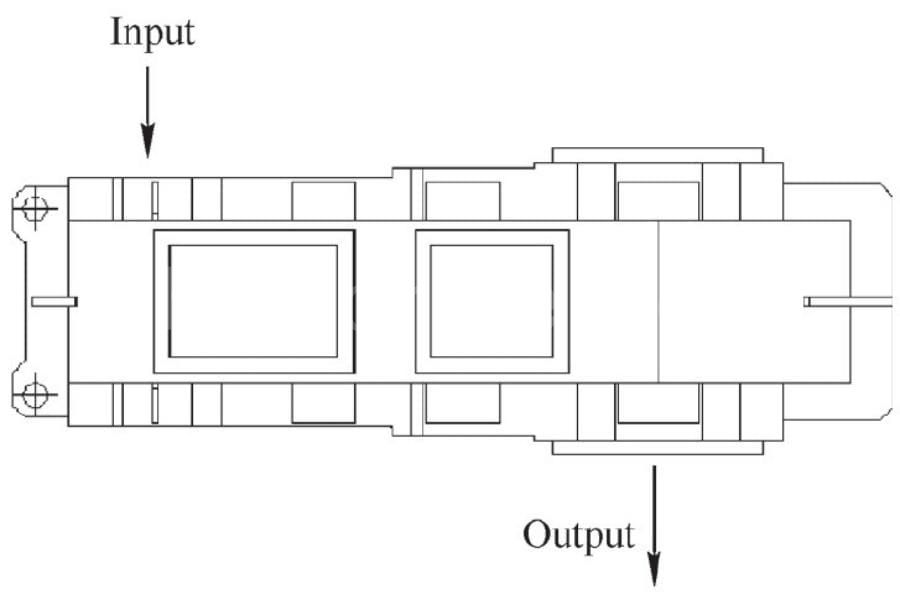
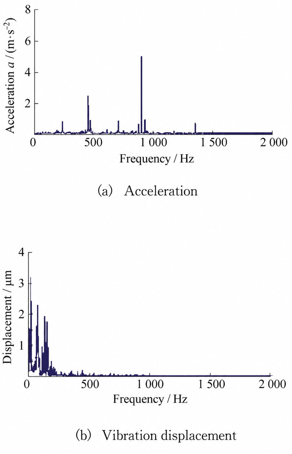
Το Σχήμα 4 δείχνει τη δομή του μειωτήρα. Οι θέσεις έδρασης των ρουλεμάν στα άκρα εισόδου και εξόδου επιλέγονται για τον υπολογισμό και λαμβάνονται οι χαρακτηριστικές καμπύλες ταλάντωσης στο πεδίο συχνότητας για σφάλμα εκκεντρότητας 20 μm.
Όπως φαίνεται στο Σχήμα 5, αφού ληφθεί υπόψη το σφάλμα εκκεντρότητας, η συχνότητα περιστροφής του άξονα εισόδου των 25 Hz επηρεάζει άλλα ζεύγη γραναζιών σε διαφορετικά στάδια, ειδικά στην καμπύλη μετατόπισης. Ο υπολογισμός του θορύβου με βάση τα αποτελέσματα των κραδασμών μπορεί στη συνέχεια να δείξει την επίδραση του σφάλματος εκκεντρότητας στον μη φυσιολογικό θόρυβο του μειωτήρα.
3 Πρόβλεψη Ακτινοβολούμενου Θορύβου για Γέφυρα Άξονα Φορείου
3.1 Ακουστικό μοντέλο
Σύμφωνα με τις αναφερόμενες αναφορές, η ακουστική ανήκει στον τομέα της έρευνας ρευστών. Επομένως, η εξίσωση ακουστικού κύματος μπορεί να μελετηθεί από την εξίσωση συνέχειας ρευστού. Όσον αφορά την κατάσταση του μέσου, μπορεί να εκφραστεί ως:

Στον τύπο, ρ, v, π, και μικρό είναι η πυκνότητα, η ταχύτητα, η ηχητική πίεση και η εντροπία του αέρα, ενώ φά και q είναι εξωτερικές πηγές διέγερσης του αέρα.
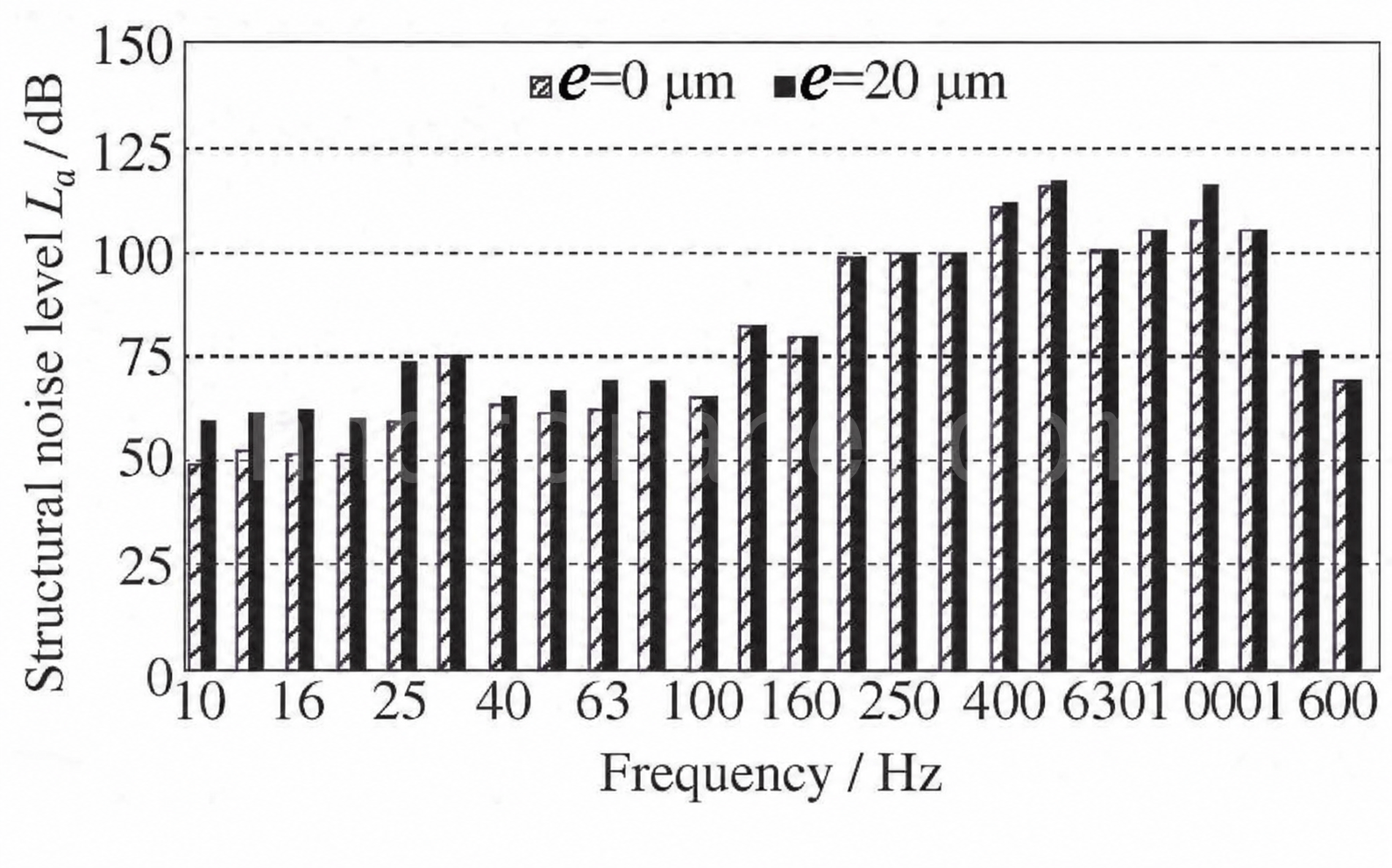
Με βάση την απόκριση κραδασμών του μειωτήρα γερανού, το αποτέλεσμα υπολογισμού επιτάχυνσης υποβάλλεται σε επεξεργασία με μετασχηματισμό Fourier και επεξεργασία ενός τρίτου οκτάβας. Το αποτέλεσμα υπολογισμού δομικού θορύβου της έδρας εδράνου υψηλής ταχύτητας του μειωτήρα φαίνεται στο Σχήμα 6.
Όταν λαμβάνεται υπόψη το σφάλμα εκκεντρότητας, ο δομικός θόρυβος του μειωτήρα αυξάνεται πιο καθαρά στην περιοχή χαμηλών συχνοτήτων 0-100 Hz. Σύμφωνα με την ακουστική θεωρία, μια διαφορά 6 dB αντιπροσωπεύει μια εφάπαξ διαφορά στο επίπεδο ενέργειας. Στο Σχήμα 6, η διαφορά θορύβου σε ορισμένες ζώνες συχνοτήτων φτάνει περίπου τις τρεις φορές, δείχνοντας ότι το σφάλμα εκκεντρότητας έχει σημαντική επίδραση στις δονήσεις χαμηλών συχνοτήτων του μειωτήρα. Σαφείς κορυφές εμφανίζονται επίσης στα 500 Hz και 1.000 Hz, οι οποίες προκαλούνται από τη συχνότητα εμπλοκής των γραναζιών του σταδίου εισόδου.
3.2 Μέτρα για τη μείωση του ασυνήθιστου θορύβου
Η εκκεντρότητα των 20 μm που χρησιμοποιείται στον υπολογισμό επιλέγεται σύμφωνα με τον βαθμό ακρίβειας του κιβωτίου ταχυτήτων. Σε πραγματική λειτουργία, ενδέχεται να υπάρχει μεγαλύτερο σφάλμα εκκεντρότητας, το οποίο μπορεί να επηρεάσει σημαντικά τη μείωση των κραδασμών και του θορύβου του μειωτήρα. Με βάση την ανάλυση και τα συμπεράσματα αυτού του άρθρου, ο μη φυσιολογικός θόρυβος μπορεί να μειωθεί από τις ακόλουθες απόψεις:
1. Βελτίωση της επιλογής της ακρίβειας μετάδοσης γραναζιών. Πολλές γερανογέφυρες χρησιμοποιούν ελικοειδή γρανάζια κατηγορίας 8. Οι συνηθισμένοι μειωτήρες γερανών δεν λαμβάνουν υπόψη την επακόλουθη ακριβή επεξεργασία, επομένως το σφάλμα εκκεντρότητας μπορεί να οδηγήσει σε υψηλότερο ακτινοβολούμενο θόρυβο. Εάν η απόσβεση και η λείανση των γραναζιών, η λείανση της επιφάνειας των δοντιών ή παρόμοια επεξεργασία ληφθούν υπόψη στο τελικό στάδιο φινιρίσματος, μπορεί να επιτευχθεί ακρίβεια κατηγορίας 7 ή 6. Αυτή μπορεί να είναι μια καλύτερη επιλογή για συνεργεία με αυστηρότερες απαιτήσεις ελέγχου θορύβου.
2. Βελτιστοποίηση του συστήματος μετάδοσης κίνησης με γρανάζια. Από την άποψη του συστήματος μετάδοσης κίνησης, θα πρέπει να λαμβάνονται υπόψη περιορισμοί όπως η αντοχή στην κόπωση λόγω επαφής με κλειστό γρανάζι, ο λόγος μετάδοσης κίνησης και ο συντελεστής πλάτους όψης. Ένας γενετικός αλγόριθμος μπορεί να χρησιμοποιηθεί για να προσαρμόσει ελαφρώς τη μονάδα γραναζιού, το πλάτος των δοντιών και τον αριθμό των δοντιών του κινητήριου γραναζιού χωρίς να αλλάξει σημαντικά αυτούς τους περιορισμούς, έτσι ώστε η συχνότητα μετάδοσης θορύβου του μειωτήρα να διατηρείται μακριά από το εύρος που είναι ευαίσθητο στην ανθρώπινη ακοή. Η συγκεκριμένη μέθοδος απαιτεί αντίστοιχα προγράμματα και δοκιμές για την επαλήθευση των βέλτιστων παραμέτρων του γραναζιού.
3. Βελτιστοποίηση της δομής του περιβλήματος του μειωτήρα. Ο κύριος σκοπός της βελτιστοποίησης του περιβλήματος είναι η βελτίωση της φυσικής του συχνότητας. Οι πρώτες δέκα φυσικές συχνότητες ενός πολυβάθμιου συστήματος μετάδοσης παράλληλου άξονα είναι γενικά χαμηλές, συνήθως στην περιοχή των 50-500 Hz, και μπορούν εύκολα να επικαλυφθούν με τη συχνότητα περιστροφής του κινητήριου μηχανισμού και τις αρμονικές του, προκαλώντας συντονισμό. Με βάση τη δομή του μειωτήρα, το υλικό μπορεί να αφαιρεθεί από ορισμένες θέσεις. Αυτό όχι μόνο εξοικονομεί κόστος υλικού, αλλά μπορεί επίσης να αυξήσει τη φυσική συχνότητα του μειωτήρα και να μειώσει αποτελεσματικά τον ανώμαλο θόρυβο που προκαλείται από σφάλμα εκκεντρότητας.
4 Συμπέρασμα
Αυτό το άρθρο λαμβάνει ως ερευνητικό αντικείμενο μια γερανογέφυρα και τον μειωτήρα της και αναλύει την επίδραση του σφάλματος εκκεντρότητας του ζεύγους γραναζιών στον μη φυσιολογικό θόρυβο του μειωτήρα. Τα συμπεράσματα είναι τα εξής:
1. Όταν λαμβάνεται υπόψη το σφάλμα εκκεντρότητας, η γωνιακή ταχύτητα του κινούμενου γραναζιού παρουσιάζει κανονική διακύμανση. Το εύρος διακύμανσης συγκεντρώνεται μεταξύ 40,5-41,5 rad/s. Αντανακλά τη συχνότητα περιστροφής του άξονα εισόδου των 25 Hz και τη συχνότητα περιστροφής εξόδου του κινούμενου γραναζιού των 6,5 Hz και συνεχίζει να επηρεάζει την επόμενη μετάδοση του ζεύγους γραναζιών.
2. Υπό σφάλμα εκκεντρότητας, ο δομικός θόρυβος του μειωτήρα αυξάνεται πιο έντονα στην περιοχή χαμηλών συχνοτήτων 0-100 Hz. Η μέγιστη διαφορά φτάνει τα 15 dB και η στάθμη θορύβου αυξάνεται κατά 2,5 φορές, εντείνοντας σαφώς τον ανώμαλο θόρυβο του κιβωτίου ταχυτήτων.
3. Προτείνονται αρκετές λύσεις, όπως η βελτίωση της ακρίβειας του κιβωτίου ταχυτήτων, η βελτιστοποίηση των παραμέτρων των γραναζιών και η αύξηση της ιδιοσυχνότητας της δομής.

Είμαι η Cindy, με 10ετή εργασιακή εμπειρία στη βιομηχανία γερανών και συσσωρευμένη πληθώρα επαγγελματικών γνώσεων. Έχω επιλέξει τους ικανοποιητικούς γερανούς για 500+ πελάτες. Εάν έχετε οποιεσδήποτε ανάγκες ή ερωτήσεις σχετικά με τους γερανούς, μη διστάσετε να επικοινωνήσετε μαζί μου, θα χρησιμοποιήσω την τεχνογνωσία και την πρακτική εμπειρία μου για να σας βοηθήσω να λύσετε το πρόβλημα!
Στείλτε το ερώτημά σας
- ΗΛΕΚΤΡΟΝΙΚΗ ΔΙΕΥΘΥΝΣΗ: sales@hndfcrane.com
- WhatsApp: +86 191 3738 6654
- Τηλεγράφημα: +86 191 3738 6654
- Τηλ: +86-373-581 8299
- Φαξ: +86-373-215 7000
- Προσθήκη: Changnao Industrial District, πόλη Xinxiang, επαρχία Henan, Κίνα
 WeChat
- Εναέριοι γερανοί
- Γερανοί διπλής δοκού
- Εναέριοι γερανοί μονής δοκού
- Γερανοί μονής δοκού ευρωπαϊκού τύπου
- Εναέριοι γερανοί με αντιεκρηκτική προστασία
- Γερανοί αρπαγής και μαγνητικός
- Μονοτροχοί Γερανοί
- Εναέριοι Γερανοί Χυτηρίου
- Γερανοί σταθμού εργασίας: Ελαφρύς σχεδιασμός, εύκολη εγκατάσταση και εύκολη λειτουργία
- Γερανοί Jib
- Επιτοίχιοι γερανοί φλόκων
- Τοίχοι Ταξιδιωτικοί Γερανοί Jib
- Ελεύθεροι όρθιοι γερανοί φλόκων
- Γερανοί αλουμινίου με βραχίονα: Ελαφρύς, ομαλός περιστρεφόμενος βραχίονας για εύκολη ανύψωση
- Γερανοί με ζυγοστάθμιση: Αποδοτική ελαφριά ανύψωση για μηχανική συναρμολόγηση σε μικρές αποστάσεις
- Χειροκίνητες Ελεύθερες Γερανογέφυρες Jib: Αποδοτικές Λύσεις Χειροκίνητης Ανύψωσης για Εργασίες σε Περιορισμένο Χώρο
- Ηλεκτρικοί γερανοί με βραχίονα ανύψωσης: Πλήρως ηλεκτρική λύση για γρήγορη ανύψωση υψηλής χωρητικότητας
- Αρθρωτοί γερανοί Jib: Ανύψωση ακριβείας με ευελιξία διπλού βραχίονα
- Γερανός ατσάλινων σκελετών
- Διδοκοί Πυλωτοί Γερανοί
- Ημιπυλωτοί Γερανοί
- Μονοδοκοί Πυλωτοί Γερανοί
- Δικτυωτοί Πυλωτοί Γερανοί
- Πυλωτοί Γερανοί Εμπορευματοκιβωτίων
- Ρυθμιζόμενοι Πυλωτοί Γερανοί
- Φορητοί Πυλωτοί Γερανοί
- Ευρωπαϊκοί γερανοί γερανογέφυρων
- Βιομηχανίες
- Γενική Βιομηχανία
- Χειρισμός Απορριμμάτων
- Προκατασκευασμένο
- Εξουσία
- Πέτρα
- Χαρτοποιία
- Παραγωγή Μετάλλων
- Κατασκευή Γέφυρας
- Γερανοί λιμένων: Για χειρισμό εμπορευματοκιβωτίων και χύδην υλικών
- Γερανογέφυρες για τη βιομηχανία πετρελαίου και φυσικού αερίου: Βελτίωση της λειτουργικής αποδοτικότητας
- Θαλάσσιοι Γερανοί για Αποδοτική Φόρτωση Φορτίου σε Πλοία
- Γερανογέφυρες για την αυτοκινητοβιομηχανία: Αποδοτικές λύσεις αυτοματισμού
- Ηλεκτρικά Ανυψωτικά
- Ηλεκτρικά συρματόσχοινα ανυψωτικά
- Ηλεκτρικά Ανυψωτικά Αλυσίδας
- Ηλεκτρικά Ανυψωτικά Ευρωπαϊκού Τύπου
- Ευρωπαϊκοί ηλεκτρικοί ανυψωτήρες αλυσίδας: Ομαλή λειτουργία, χαμηλός θόρυβος και ενεργειακή απόδοση
- Χειροκίνητα βαρούλκα με μοχλό: Ιδανικά για εργασίες έλξης και ανύψωσης
- Χειροκίνητα βαρούλκα με αλυσίδα: Χειροκίνητη ανύψωση για περιοχές χωρίς ρεύμα
- Ηλεκτρικά ανυψωτικά με χαμηλό ύψος κεφαλής: Συμπαγής σχεδιασμός για μέγιστη απόδοση χώρου
- Πνευματικά βαρούλκα αλυσίδας: Ομαλό χειρισμό για βιομηχανική χρήση
- Χειροκίνητα βαρούλκα αλυσίδας με αντιεκρηκτική προστασία: Κατασκευή από κράμα χαλκού με αντοχή σε σπινθήρες για επικίνδυνες περιοχές
- Ηλεκτρικά βαρούλκα αλυσίδας με αντιεκρηκτική προστασία για ανύψωση σε επικίνδυνες περιοχές
- Σχετικά με
- Υποθέσεις
- Νέα
- Συχνές ερωτήσεις
- Κατεβάστε
- Blogs
- Εργαλεία υπολογισμού φορτίου τροχού γερανού στο διαδίκτυο
- Πανόραμα VR
- Επικοινωνήστε μαζί μας
- ΗΛΕΚΤΡΟΝΙΚΗ ΔΙΕΥΘΥΝΣΗ: sales@hndfcrane.com
- WhatsApp: +86 191 3738 6654
- Τηλεγράφημα: +86 191 3738 6654
- Τηλ: +86-373-581 8299
-