-
industrier
-
Allmän tillverkning
-
Avfallshantering
-
Förtillverkad
-
Kraft
-
Sten
-
Papperstillverkning
-
Metallproduktion
-
Brokonstruktion
-
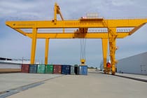
Hamnkranar: För container- och bulkhantering
-
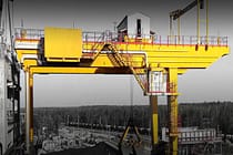
Traverskranar för olje- och gasindustrin: Förbättra driftseffektiviteten
-
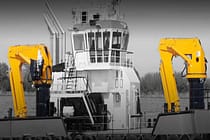
Marina kranar för effektiv lastning på fartyg
-
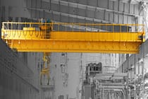
Traverskranar för fordonsindustrin: Effektiva automationslösningar
-
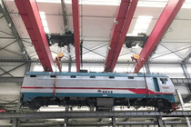
Traverskranlösningar för järnvägar: Spårläggning, underhåll av rullande materiel och containerhantering
-
Traverskranar för livsmedel och drycker: Tillförlitliga lösningar för effektiv hantering
-
Traverskranar för effektiv tillverkning av cement, glas, tegel och prefabricerad betong
-
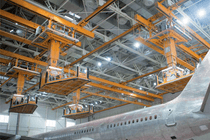
Traverskranar för flygindustrin: Flygplansunderhåll och montering
-
Traverskranar för flyg- och rymdfart: Precisionslyft för raketuppskjutning och transport
-
-
Produkter
-
Luftkranar
-
Enbalks traverskranar
-
Dubbelbalk överheadkranar
-
Traverskranar av europeisk typ med en balk
-
Europeiska dubbelbalkskranar
-
Explosionssäkra luftkranar
-
Grab och Magnetiska Overhead Kranar
-
Monorail kranar
-
Gjuteri kranar
-
Isolering traverser
-
Låg takhöjd traverskranar
-
Ta tag i luftkranar
-
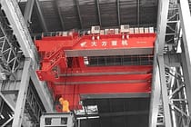
Slev traverskranar
-
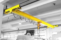
Underhängda traverskranar
-
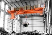
Elektromagnetiska traverskranar
-
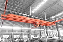
Arbetsstationskranar: Lätt design, enkel installation och problemfri drift
-
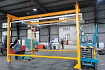
Fristående arbetsstationsbrokranar
-
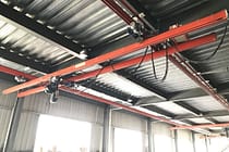
Takmonterad brokran
-
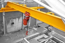
Manuella traverskranar
-
-
Gantry kranar
-
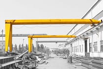
Semi portalkranar
-
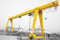
Enkelbalks portalkranar
-
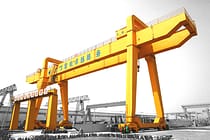
Dubbelbalk portalkranar
-
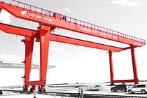
Container portalkranar
-
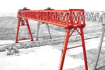
Truss portalkranar
-
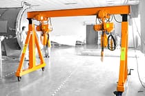
Justerbara portalkranar
-
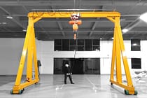
Bärbara portalkranar
-
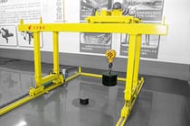
Europeiska portalkranar
-
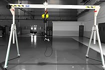
Portalkranar i aluminium
-
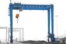
Gummi däckade container portalkranar
-
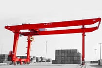
Rälsmonterade containerportalkranar
-
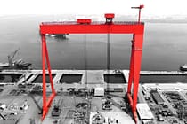
Shipyard Gantry Crane
-
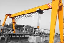
Europeiska portalkranar med en balk
-
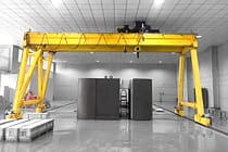
Europeiska portalkranar med dubbla balkar
-
- Fockkranar
- Specialkranar
- Elektriska lyftar
- Transfervagnar
-
Luftkranar
-
Kran delar
-
Ta tag i hinkar
-
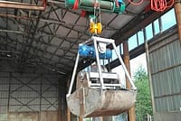
Elektrisk gripskopa i rostfritt stål
-
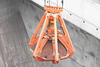
Mekaniska fyra rep av apelsinskal
-
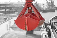
Mekanisk gripskopa med fyra rep
-
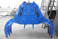
Elektrohydrauliska rektangulära grepp
-
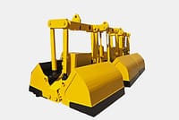
Elektrohydrauliska Clamshell-grepp
-
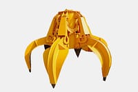
Elektrohydrauliska apelsinskalgrepp, hydrauliska kaktusgrepp
-
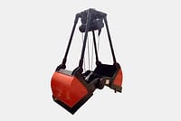
Elmotorgrepp
-
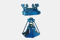
Elektrisk Monorail gripskopa med Monorail-lyft
-
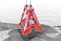
Fjärrkontroll Clamshell Grip
-
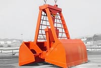
Mekaniska grepp med två rep
-
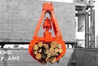
Timmergriper
-
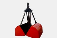
Enkeltrep
-
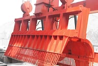
Rengöringsmaskiner för papperskorgen
-
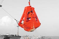
Muddringsgrepp
-
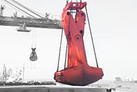
Trimningsgrepp
-
- Kranspridare
- Kran reservdelar
- Kranhjul
-
Ta tag i hinkar
- Företag
- Kontakt
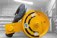
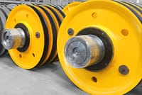
-
industrier
-
Allmän tillverkning
-
Avfallshantering
-
Förtillverkad
-
Kraft
-
Sten
-
Papperstillverkning
-
Metallproduktion
-
Brokonstruktion
-
Hamnkranar: För container- och bulkhantering
-
Traverskranar för olje- och gasindustrin: Förbättra driftseffektiviteten
-
Marina kranar för effektiv lastning på fartyg
-
Traverskranar för fordonsindustrin: Effektiva automationslösningar
-
Traverskranlösningar för järnvägar: Spårläggning, underhåll av rullande materiel och containerhantering
-
Traverskranar för livsmedel och drycker: Tillförlitliga lösningar för effektiv hantering
-
Traverskranar för effektiv tillverkning av cement, glas, tegel och prefabricerad betong
-
Traverskranar för flygindustrin: Flygplansunderhåll och montering
-
Traverskranar för flyg- och rymdfart: Precisionslyft för raketuppskjutning och transport
-
-
Produkter
-
Luftkranar
-
Enbalks traverskranar
-
Dubbelbalk överheadkranar
-
Traverskranar av europeisk typ med en balk
-
Europeiska dubbelbalkskranar
-
Explosionssäkra luftkranar
-
Grab och Magnetiska Overhead Kranar
-
Monorail kranar
-
Gjuteri kranar
-
Isolering traverser
-
Låg takhöjd traverskranar
-
Ta tag i luftkranar
-
Slev traverskranar
-
Underhängda traverskranar
-
Elektromagnetiska traverskranar
-
Arbetsstationskranar: Lätt design, enkel installation och problemfri drift
-
Fristående arbetsstationsbrokranar
-
Takmonterad brokran
-
Manuella traverskranar
-
-
Gantry kranar
-
Semi portalkranar
-
Enkelbalks portalkranar
-
Dubbelbalk portalkranar
-
Container portalkranar
-
Truss portalkranar
-
Justerbara portalkranar
-
Bärbara portalkranar
-
Europeiska portalkranar
-
Portalkranar i aluminium
-
Gummi däckade container portalkranar
-
Rälsmonterade containerportalkranar
-
Shipyard Gantry Crane
-
Europeiska portalkranar med en balk
-
Europeiska portalkranar med dubbla balkar
-
- Fockkranar
- Specialkranar
- Elektriska lyftar
- Transfervagnar
-
Luftkranar
-
Kran delar
-
Ta tag i hinkar
-
Elektrisk gripskopa i rostfritt stål
-
Mekaniska fyra rep av apelsinskal
-
Mekanisk gripskopa med fyra rep
-
Elektrohydrauliska rektangulära grepp
-
Elektrohydrauliska Clamshell-grepp
-
Elektrohydrauliska apelsinskalgrepp, hydrauliska kaktusgrepp
-
Elmotorgrepp
-
Elektrisk Monorail gripskopa med Monorail-lyft
-
Fjärrkontroll Clamshell Grip
-
Mekaniska grepp med två rep
-
Timmergriper
-
Enkeltrep
-
Rengöringsmaskiner för papperskorgen
-
Muddringsgrepp
-
Trimningsgrepp
-
- Kranspridare
- Kran reservdelar
- Kranhjul
-
Ta tag i hinkar
- Företag
- Kontakt



Overhead Crane Wheel Types and Inspection
Innehållsförteckning
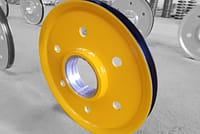
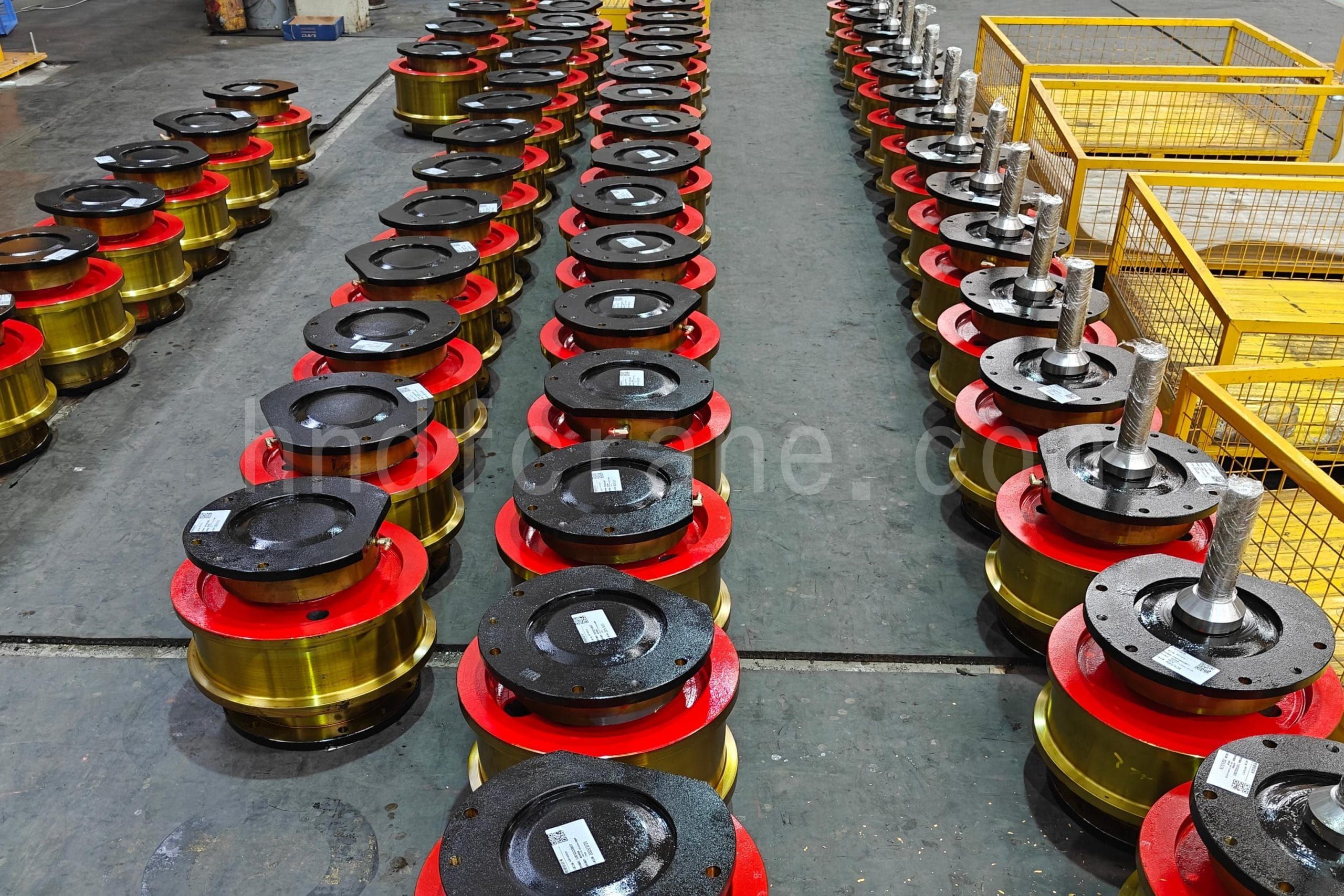
Overhead crane wheels support the crane and its load while enabling travel along the rails. Their tread profiles, flange designs, and mounting arrangements affect travel stability and wear. This guide covers common overhead crane wheel types, wheel assemblies, bearing supports, horizontal guide rollers, and key inspection points.
Common Overhead Crane Wheel Types
Classification by application
- Rail-running wheels: Usually used on the bridge and trolley travelling mechanisms of overhead and gantry cranes. They have the widest range of applications.
- Suspended crane wheels: Run on the lower flange of an I-beam or box girder in single-girder cranes.
Classification by tread profile
- Cylindrical-tread wheels: The most common type.
- Conical-tread wheels: A common taper is 1:10. Concentrated-drive bridge-crane travelling mechanisms sometimes use conical-tread wheels to improve travel performance under skewing conditions. Hoist trolleys running on the lower flange of an I-beam may also use conical wheels.
Classification by flange arrangement
- Double-flange wheels: Commonly used for the bridge travelling wheels of overhead and gantry cranes.
- Single-flange wheels: Commonly used for overhead-crane trolley wheels.
- Flangeless wheels: These wheels have no flange to provide lateral restraint, so derailment is possible and their application is limited. Flangeless wheels may be used only when horizontal guide rollers are installed on both sides of the wheels.
Wheel flanges are normally provided to prevent derailment. The flange height is approximately 15–25 mm and the flange has a 1:5 slope. The exact dimensions must be determined from the wheel drawing, crane type, and applicable standard. Bridge-crane travelling mechanisms commonly use double-flange wheels. When the trolley gauge is small, an appropriate flange arrangement may also be used to reduce the amount of wheel machining.
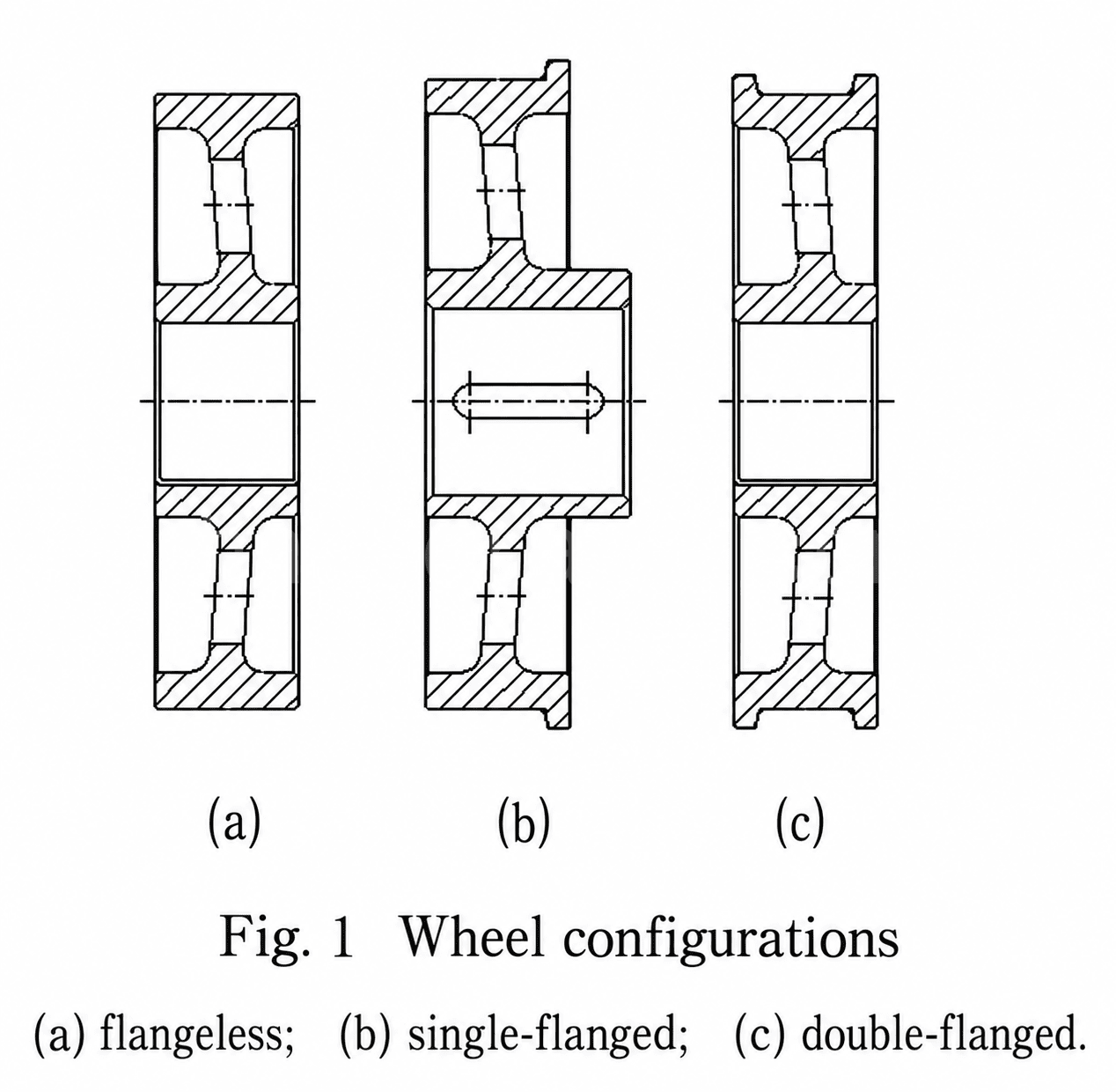
Wheel-Support Arrangements
Crane wheel-support arrangements can generally be divided into two types:
- Fixed-axle arrangements;
- Rotating-axle arrangements.
The specific arrangement should be selected according to the travelling mechanism, wheel-set layout, and maintenance requirements of the crane.
Wheel-Set Components and Types
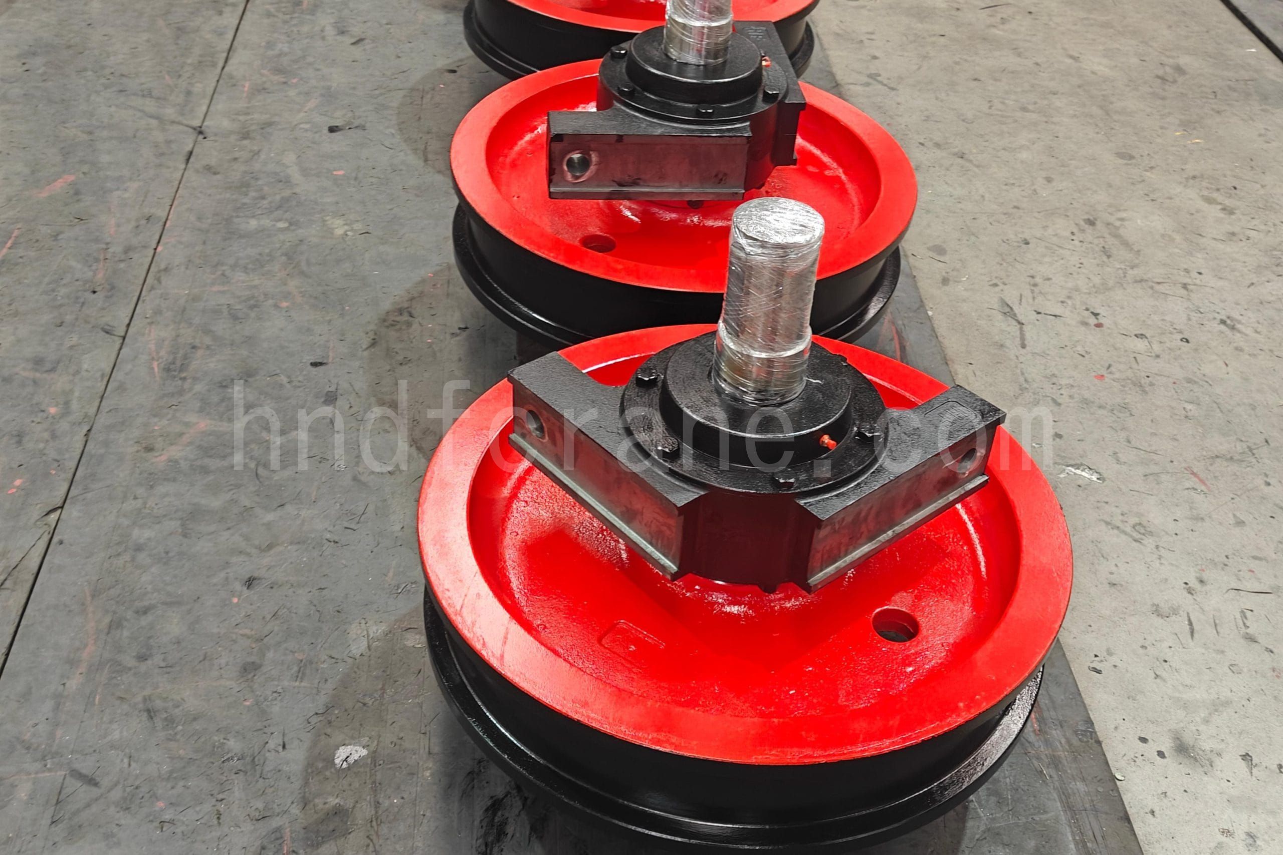
A wheel set is an important component of a travelling mechanism. It normally consists of a wheel, wheel axle, bearings, bearing housing, end covers, and fasteners.
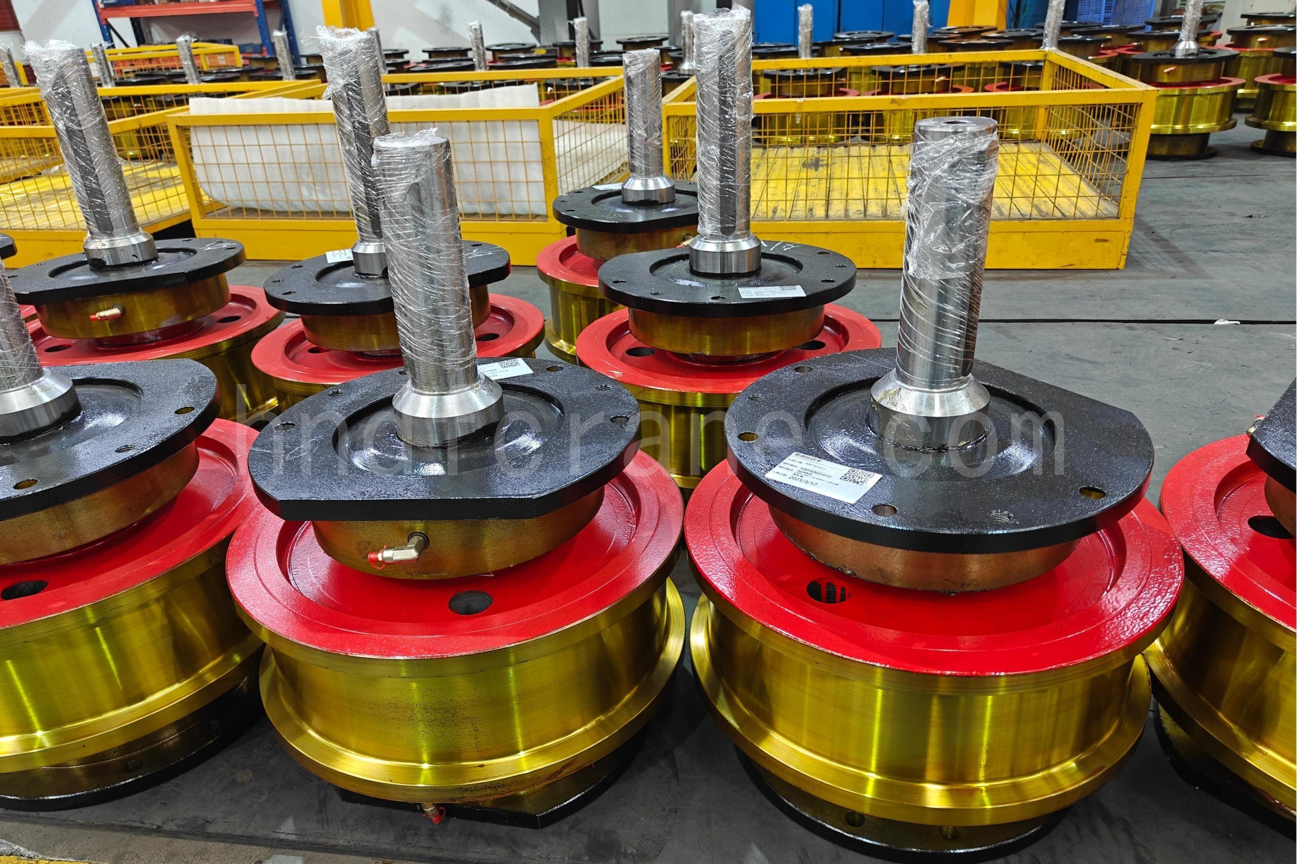
Common wheel materials include ZG340-640, CL60, and 42CrMo. Other cast steels, rolled steels, or forged steels may also be selected according to the design requirements. After machining, the hardness of the tread and the inner side of the flange is HB 300–380. When the wheel diameter is less than 400 mm, the hardness at approximately 15 mm below the surface, or at approximately 20 mm below the surface when the wheel diameter is greater than 400 mm, should not be lower than HB 260. These material and hardness data must be checked against the applicable wheel standard, drawing, and manufacturing process.
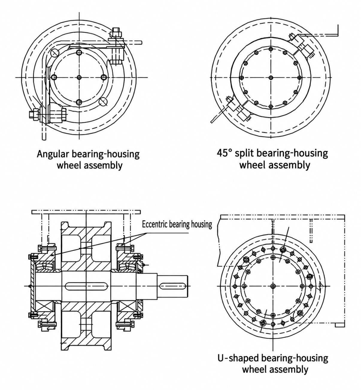
Wheel-set bearing housings commonly use angular bearing boxes. A 45° split bearing housing or a U-shaped bearing housing may also be used according to the design.
A U-shaped bearing housing allows the wheel installation position to be adjusted within a certain range. By adjusting the rotation angle of an eccentric bearing housing, the wheel height, lateral position, and skew can be adjusted by approximately ±0.5 mm. The actual adjustment range must be determined from the equipment design and field measurements.
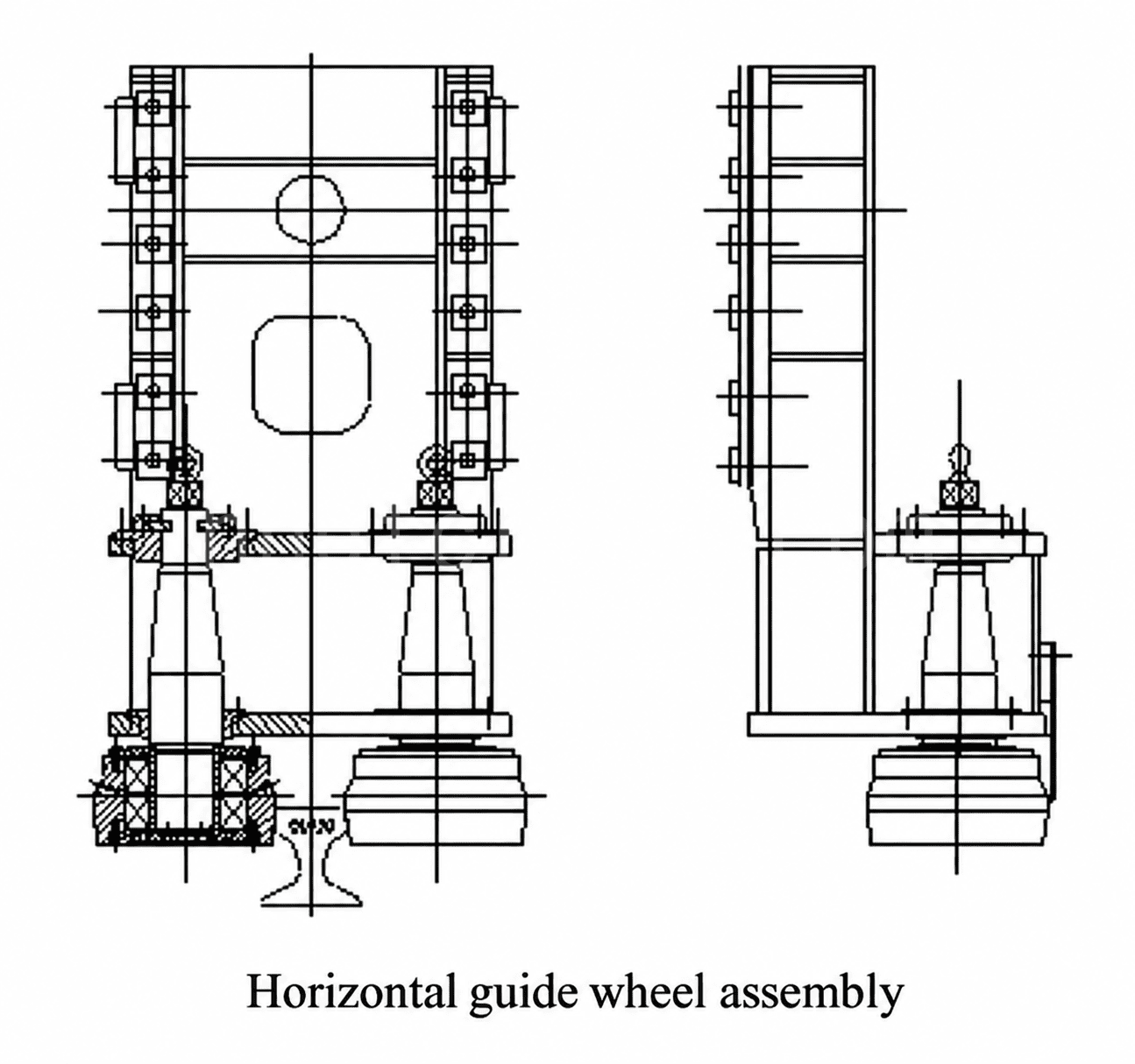
Horizontal Guide-Roller Arrangements
Horizontal guide-roller arrangements can usually be installed at both ends of the end carriage on one side of a crane bridge. They help reduce skewing and rail gnawing during travel.
The clearance between the guide rollers and the rail can be adjusted to compensate for guide-roller wear or to correct the relative position. The guide-roller axle is usually eccentric. Rotating the eccentric axle adjusts the position, after which a bolted pressure plate fixes the setting. The horizontal adjustment is approximately ±5 mm; the exact value must be determined from the structural drawing and operating conditions.
Key Points for Overhead Crane Wheel Inspection
Overhead crane wheels should be inspected regularly in accordance with the equipment maintenance program and applicable standards.
- Use a small hammer to check the wheel tread, flange, and spokes for cracks. If a crack is found, stop using the wheel and replace or repair it according to the applicable technical requirements.
- Check whether the wheel tread is flat and even. If wear has formed a step, machine the wheel or replace it according to the remaining dimensions and repair conditions.
- Check flange wear. When the wear exceeds 50% of the original flange thickness, evaluate the wheel and consider replacement. The actual discard limit must be determined from the applicable standard, the manufacturer’s drawing, and the safety assessment.
- During a major crane overhaul, remove the wheel set for cleaning and inspection. Check the bearings, seals, and lubrication. Whether all bearings need to be replaced should be decided from the inspection results and maintenance procedure.
- Check whether the fit between the wheel axle and wheel bore is loose. If looseness is found, evaluate whether to replace the wheel axle or related components. Looseness or damage in the coupling, gear bore, or keyway should also be handled according to the maintenance requirements.
- Check angular bearing boxes and other bearing housings for cracks, deformation, and loose connections. Replace cracked parts.
Measures to Extend Overhead Crane Wheel Service Life
Overhead crane wheels are load-bearing components. Poor rail installation and wheel manufacturing deviations can cause skewing and slipping during operation, accelerating wear and leading to premature replacement. The following three measures may help extend wheel service life, subject to the crane’s design requirements:
- Increase the wheel flange height.
- Use conical wheels with a greater tread taper as drive wheels.
- Apply deep-hardening heat treatment to the wheel tread to improve wear resistance. However, excessive tread hardness can cause severe rail wear. The typical hardness range for the wheel tread and inner flange surfaces is 300–380 HB.
Slutsats
Extending overhead crane wheel service life requires proper wheel selection, manufacturing quality, accurate installation, and well-maintained rails. Abnormal flange wear, tread damage, or rail skewing should prompt an investigation into the underlying cause. Correct wheel and rail matching, regular inspections, and timely maintenance can help reduce premature wear, downtime, and replacement costs.
Looking to select or replace overhead crane wheels? Share your crane model, wheel load, wheel dimensions, and rail specifications with us to get a wheel assembly solution suited to your operating conditions.

Jag är Cindy, med 10 års arbetslivserfarenhet inom kranbranschen och samlat på mig en mängd professionell kunskap. Jag har valt de tillfredsställande kranarna för 500+ kunder. Om du har några behov eller frågor om kranar är du välkommen att kontakta mig, jag kommer att använda min expertis och praktiska erfarenhet för att hjälpa dig att lösa problemet!
Skicka din förfrågan
- E-post: sales@hndfcrane.com
- WhatsApp: +86 191 3738 6654
- Telegram: +86 191 3738 6654
- Tel: +86-373-581 8299
- Fax: +86-373-215 7000
- Lägg till: Changnao Industrial District, Xinxiang City, Henan-provinsen, Kina
 WeChat
- Luftkranar
- Dubbelbalk överheadkranar
- Enbalks traverskranar
- Traverskranar av europeisk typ med en balk
- Explosionssäkra luftkranar
- Grab och Magnetiska Overhead Kranar
- Monorail kranar
- Gjuteri kranar
- Arbetsstationskranar: Lätt design, enkel installation och problemfri drift
- Fockkranar
- Väggmonterade kranar
- Väggfockkranar
- Fristående jibbkranar
- Aluminiumsvängkranar: Lätt, smidig roterande arm för enkel lyftning
- Balanssvängkranar: Effektiva lätta lyft för mekanisk montering över korta avstånd
- Manuella fristående svängkranar: Effektiva manuella lyftlösningar för operationer med begränsat utrymme
- Elektriska fristående svängkranar: Helelektrisk lösning för högkapacitets snabba lyft
- Ledsvängkranar: Precisionslyft med dubbelarmsflexibilitet
- Gantry kranar
- Dubbelbalk portalkranar
- Semi portalkranar
- Enkelbalks portalkranar
- Truss portalkranar
- Container portalkranar
- Justerbara portalkranar
- Bärbara portalkranar
- Europeiska portalkranar
- industrier
- Allmän tillverkning
- Avfallshantering
- Förtillverkad
- Kraft
- Sten
- Papperstillverkning
- Metallproduktion
- Brokonstruktion
- Hamnkranar: För container- och bulkhantering
- Traverskranar för olje- och gasindustrin: Förbättra driftseffektiviteten
- Marina kranar för effektiv lastning på fartyg
- Traverskranar för fordonsindustrin: Effektiva automationslösningar
- Elektriska lyftar
- Elektriska vajertelfer
- Elektriska kedjetelfer
- Elektriska lyftanordningar av europeisk typ
- Europeiska elektriska kedjetelfer: Jämn drift, lågt ljud och energieffektivitet
- Manuella lyftanordningar: Perfekta för drag- och lyftuppgifter
- Handkättingtelfrar: Manuell lyftning för områden utan ström
- Elektriska lyftanordningar med låg takhöjd: Kompakt design för maximal utrymmeseffektivitet
- Pneumatiska kedjetelfrar: Smidig hantering för industriellt bruk
- Explosionssäkra manuella kättingtelfrar: Gnistsäker kopparlegeringskonstruktion för explosionsfarliga områden
- Explosionssäkra elektriska kättingtelfrar för lyft i farliga områden
- Handla om
- Fall
- Nyheter
- Vanliga frågor
- Ladda ner
- Bloggar
- Onlineverktyg för beräkning av kranhjulslast
- VR Panorama
- Kontakta oss
- E-post: sales@hndfcrane.com
- WhatsApp: +86 191 3738 6654
- Telegram: +86 191 3738 6654
- Tel: +86-373-581 8299
-