
-
endüstriler
-
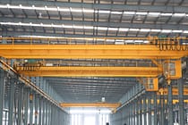
Genel İmalat
-
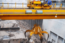
Atık İşleme
-
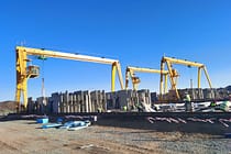
Prekast
-
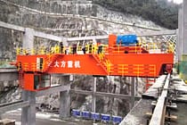
Güç
-
Taş
-
kağıt yapımı
-
metal üretimi
-
Köprü İnşaatı
-
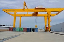
Liman Vinçleri: Konteyner ve Toplu Malzeme Elleçleme İçin
-
Petrol ve Gaz Endüstrisi için Köprülü Vinçler: Operasyonel Verimliliği Artırın
-
Gemilerde Verimli Kargo Yüklemesi için Deniz Vinçleri
-
Otomotiv Endüstrisi için Köprülü Vinçler: Verimli Otomasyon Çözümleri
-
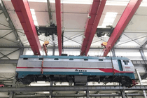
Demiryolları için Köprü Vinç Çözümleri: Ray Döşeme, Demiryolu Araçları Bakımı ve Konteyner Elleçleme
-
Gıda ve İçecekler İçin Köprü Vinçleri: Verimli Taşıma İçin Güvenilir Çözümler
-
Verimli Çimento, Cam, Tuğla ve Prefabrik Beton Üretimi için Köprülü Vinçler
-
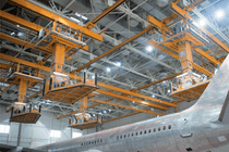
Havacılık Endüstrisi için Köprülü Vinçler: Uçak Bakımı ve Montajı
-

Havacılık ve Uzay Vinçleri: Roket Fırlatma ve Taşıma için Hassas Kaldırma
-
-
Ürünler
-
Gezer Vinçler
-
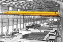
Tek Kirişli Gezer Vinçler
-
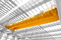
Çift Kirişli Gezer Vinçler
-
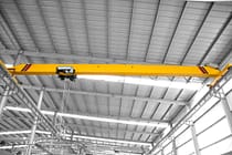
Avrupa Tipi Tek Kirişli Köprülü Vinçler
-
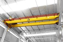
Avrupa Tipi Çift Kirişli Tavan Vinçleri
-
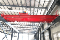
Patlama Korumalı Gezer Vinçler
-
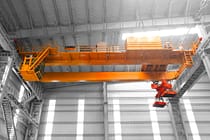
Kepçeli ve Manyetik Gezer Vinçler
-
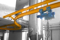
Monoray Vinçler
-
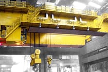
Dökümhane Vinçleri
-
Yalıtım Köprülü Vinçler
-
Alçak Tavanlı Vinçler
-
Tavan Vinçlerini Tutun
-

Pota Tavan Vinçleri
-
Alt Askılı Vinçler
-
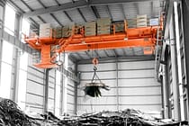
Elektromanyetik Tavan Vinçleri
-
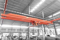
İş İstasyonu Vinçleri: Modüler Kaldırma Çözümü
-
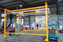
Serbest Duran İş İstasyonu Köprü Vinçleri
-
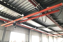
Tavana Monte Köprülü Vinç
-
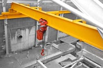
Manuel Köprülü Vinçler
-
-
Portal Vinçler
-
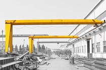
Yarı Portal Vinçler
-
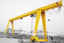
Tek Kiriş Portal Vinçler
-
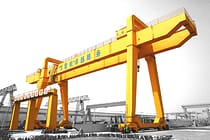
Çift Kiriş Portal Vinçler
-
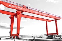
Konteyner Portal Vinçler
-
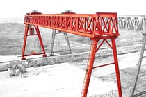
Truss Portal Vinçler
-
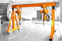
Ayarlanabilir Portal Vinçler
-
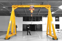
Portatif Portal Vinçler
-
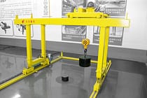
Avrupa Portal Vinçler
-
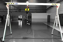
Alüminyum Portal Vinçler
-
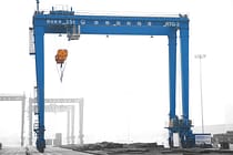
Lastik Tekerlekli Konteyner Gantry Vinçleri
-
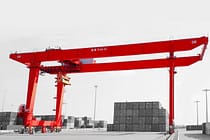
Raylı Konteyner Portal Vinçleri
-
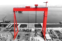
Tersane Gantry Vinç
-
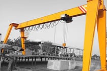
Avrupa Tek Kirişli Portal Vinçleri
-
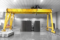
Avrupa Çift Kirişli Portal Vinçleri
-
- Pergel Vinçler
- Özel Vinçler
- Elektrikli Vinçler
- Transfer Arabaları
-
Gezer Vinçler
-
Vinç Parçaları
-
Kepçeler
-
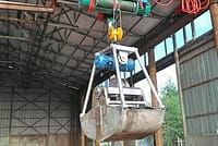
Elektrikli Paslanmaz Çelik Kepçe
-
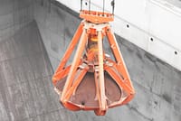
Mekanik Dört Halatlı Portakal Kabuğu Tutucular
-
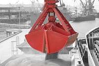
Mekanik Dört Halatlı Midye Kabuğu Kepçe Kovası
-
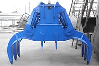
Elektro Hidrolik Dikdörtgen Tutucular
-
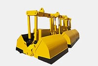
Elektro hidrolik Midye Kabuğu Tutucular
-
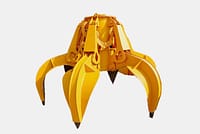
Elektro Hidrolik Portakal Kabuğu Kepçeleri, Hidrolik Kaktüs Kepçesi
-
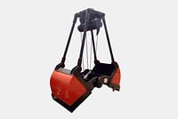
Elektrikli Motor Kepçesi
-
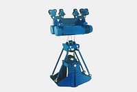
Monoray Vinçli Elektrikli Monoray Kepçe
-
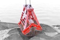
Uzaktan Kumandalı Midye Kabuğu Tutucular
-
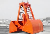
Mekanik İki Halatlı Midye Kabuğu Tutucular
-
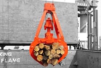
Kereste Kapmacaları
-
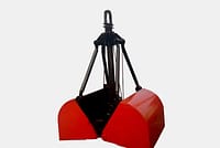
Tek Halatlı Kepçe
-
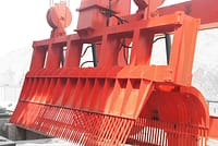
Çöp Rafı Temizleme Makineleri
-
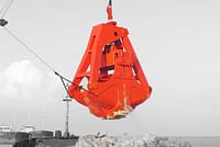
Tarama Kepçeleri
-
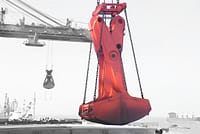
Kırpma Tutma
-
- Vinç Yayıcı
-
Vinç Yedek Parçaları
-
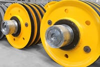
Vinç Makaraları
-
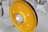
Halat Kasnakları
-
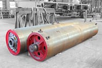
Vinç Halat Tamburu
-
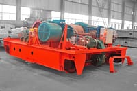
vinç arabası
-
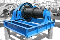
Elektrikli Vinç
-
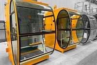
Vinç Operatör Kabini
-
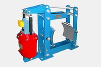
Köprülü Vinç Frenleri
-
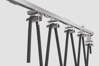
Köprülü Vinç Kabloları
-
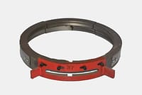
Köprülü Vinç Halat Kılavuzları
-
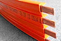
Köprü Vinç İletkenleri ve Güç Besleme Hatları
-
Köprülü Vinç Rayları
-
Köprülü Vinç Ray Klipsleri
-
Köprülü Vinç Motorları
-
Köprülü Vinç Redüktörleri
-
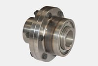
Köprülü Vinçler için Bağlantı Elemanları
-
- Vinç Tekerlekleri
-
Kepçeler
- Şirket
- Temas etmek


-
endüstriler
-
Genel İmalat
-
Atık İşleme
-
Prekast
-
Güç
-
Taş
-
kağıt yapımı
-
metal üretimi
-
Köprü İnşaatı
-
Liman Vinçleri: Konteyner ve Toplu Malzeme Elleçleme İçin
-
Petrol ve Gaz Endüstrisi için Köprülü Vinçler: Operasyonel Verimliliği Artırın
-
Gemilerde Verimli Kargo Yüklemesi için Deniz Vinçleri
-
Otomotiv Endüstrisi için Köprülü Vinçler: Verimli Otomasyon Çözümleri
-
Demiryolları için Köprü Vinç Çözümleri: Ray Döşeme, Demiryolu Araçları Bakımı ve Konteyner Elleçleme
-
Gıda ve İçecekler İçin Köprü Vinçleri: Verimli Taşıma İçin Güvenilir Çözümler
-
Verimli Çimento, Cam, Tuğla ve Prefabrik Beton Üretimi için Köprülü Vinçler
-
Havacılık Endüstrisi için Köprülü Vinçler: Uçak Bakımı ve Montajı
-
Havacılık ve Uzay Vinçleri: Roket Fırlatma ve Taşıma için Hassas Kaldırma
-
-
Ürünler
-
Gezer Vinçler
-
Tek Kirişli Gezer Vinçler
-
Çift Kirişli Gezer Vinçler
-
Avrupa Tipi Tek Kirişli Köprülü Vinçler
-
Avrupa Tipi Çift Kirişli Tavan Vinçleri
-
Patlama Korumalı Gezer Vinçler
-
Kepçeli ve Manyetik Gezer Vinçler
-
Monoray Vinçler
-
Dökümhane Vinçleri
-
Yalıtım Köprülü Vinçler
-
Alçak Tavanlı Vinçler
-
Tavan Vinçlerini Tutun
-
Pota Tavan Vinçleri
-
Alt Askılı Vinçler
-
Elektromanyetik Tavan Vinçleri
-
İş İstasyonu Vinçleri: Modüler Kaldırma Çözümü
-
Serbest Duran İş İstasyonu Köprü Vinçleri
-
Tavana Monte Köprülü Vinç
-
Manuel Köprülü Vinçler
-
-
Portal Vinçler
-
Yarı Portal Vinçler
-
Tek Kiriş Portal Vinçler
-
Çift Kiriş Portal Vinçler
-
Konteyner Portal Vinçler
-
Truss Portal Vinçler
-
Ayarlanabilir Portal Vinçler
-
Portatif Portal Vinçler
-
Avrupa Portal Vinçler
-
Alüminyum Portal Vinçler
-
Lastik Tekerlekli Konteyner Gantry Vinçleri
-
Raylı Konteyner Portal Vinçleri
-
Tersane Gantry Vinç
-
Avrupa Tek Kirişli Portal Vinçleri
-
Avrupa Çift Kirişli Portal Vinçleri
-
- Pergel Vinçler
- Özel Vinçler
- Elektrikli Vinçler
- Transfer Arabaları
-
Gezer Vinçler
-
Vinç Parçaları
-
Kepçeler
-
Elektrikli Paslanmaz Çelik Kepçe
-
Mekanik Dört Halatlı Portakal Kabuğu Tutucular
-
Mekanik Dört Halatlı Midye Kabuğu Kepçe Kovası
-
Elektro Hidrolik Dikdörtgen Tutucular
-
Elektro hidrolik Midye Kabuğu Tutucular
-
Elektro Hidrolik Portakal Kabuğu Kepçeleri, Hidrolik Kaktüs Kepçesi
-
Elektrikli Motor Kepçesi
-
Monoray Vinçli Elektrikli Monoray Kepçe
-
Uzaktan Kumandalı Midye Kabuğu Tutucular
-
Mekanik İki Halatlı Midye Kabuğu Tutucular
-
Kereste Kapmacaları
-
Tek Halatlı Kepçe
-
Çöp Rafı Temizleme Makineleri
-
Tarama Kepçeleri
-
Kırpma Tutma
-
- Vinç Yayıcı
-
Vinç Yedek Parçaları
-
Vinç Makaraları
-
Halat Kasnakları
-
Vinç Halat Tamburu
-
vinç arabası
-
Elektrikli Vinç
-
Vinç Operatör Kabini
-
Köprülü Vinç Frenleri
-
Köprülü Vinç Kabloları
-
Köprülü Vinç Halat Kılavuzları
-
Köprü Vinç İletkenleri ve Güç Besleme Hatları
-
Köprülü Vinç Rayları
-
Köprülü Vinç Ray Klipsleri
-
Köprülü Vinç Motorları
-
Köprülü Vinç Redüktörleri
-
Köprülü Vinçler için Bağlantı Elemanları
-
- Vinç Tekerlekleri
-
Kepçeler
- Şirket
- Temas etmek



Tavan Vinç Kaldırma Mekanizması Limit Anahtarları: Dört Türü ve Çalışma Prensipleri
İçindekiler
Overhead crane hoist limit switches restrict the upward travel of a hook or other load-handling device and prevent the hoisting mechanism from continuing beyond its upper position. Four types are widely used in the industry: transmission, power cut-off, heavy-hammer, and pressure-plate limit devices.
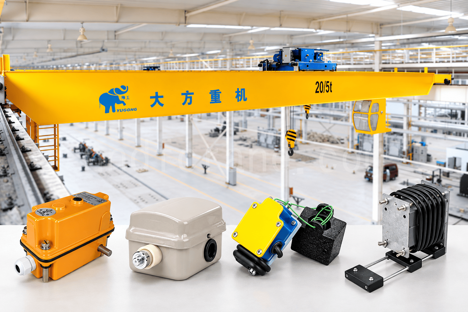
Comparison of Four Overhead Crane Hoist Limit Switches
| Tip | Main Trigger Method | Typical Installation or Application | Adjustment Requirement |
|---|---|---|---|
| Transmission | The drum shaft drives a worm gearbox and cams that actuate limit switches | Tail end of the crane drum shaft | Readjust the control range after replacing the wire rope or changing its length |
| Power cut-off | A rope-guide trigger block moves the drive rod and actuates the power cut-off switch | Electric hoist lifting mechanism | Set the upper and lower limits through the left and right stop positions; readjust after a wire-rope change |
| Heavy-hammer | The hook or load-handling device lifts the counterweight, allowing the limit switch to reset and open | Below the trolley, near the hoisting sheave block | The counterweight suspension-rope length determines the upper lifting limit |
| Pressure-plate | The hook block contacts the pressure plate and moves the switch contacts | Cranes using an electric hoist | Available in single-limit and dual-limit configurations |
1. Transmission-Type Hoisting Height Limiter
A transmission-type hoisting height limiter uses a mechanical shaft drive to actuate a protective switch in the control circuit. Its operation depends on the mechanical linkage among the drum shaft, reduction mechanism, cams, and limit switches.
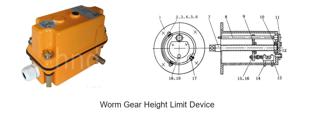
This device normally incorporates a worm gearbox with a high transmission ratio, so it is also known as a worm gear hoisting height limiter. It is generally installed at the tail end of the crane drum shaft. The drum shaft rotates the limiter’s worm, which turns the worm wheel and then the cams mounted on it. When a cam lobe contacts a limit switch, the switch controls the hoisting mechanism circuit and can cut off power to the mechanism.
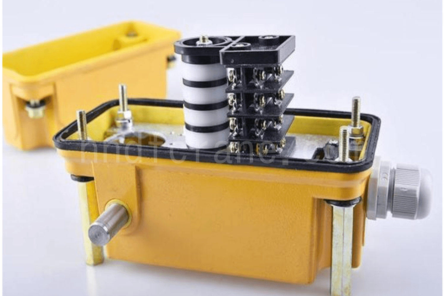
The device generally contains four cams and four limit switches. The cam lobes are staggered, which is why the device is also called a geared cam type. The four switches control:
- Deceleration before the upward travel approaches its limit.
- Stopping when the upward travel reaches its limit.
- Deceleration before the downward travel approaches its limit.
- Stopping when the downward travel reaches its limit.
Changing the positions of the cam lobes changes the actuation timing of the switches and therefore controls the lifting height and lowering depth.
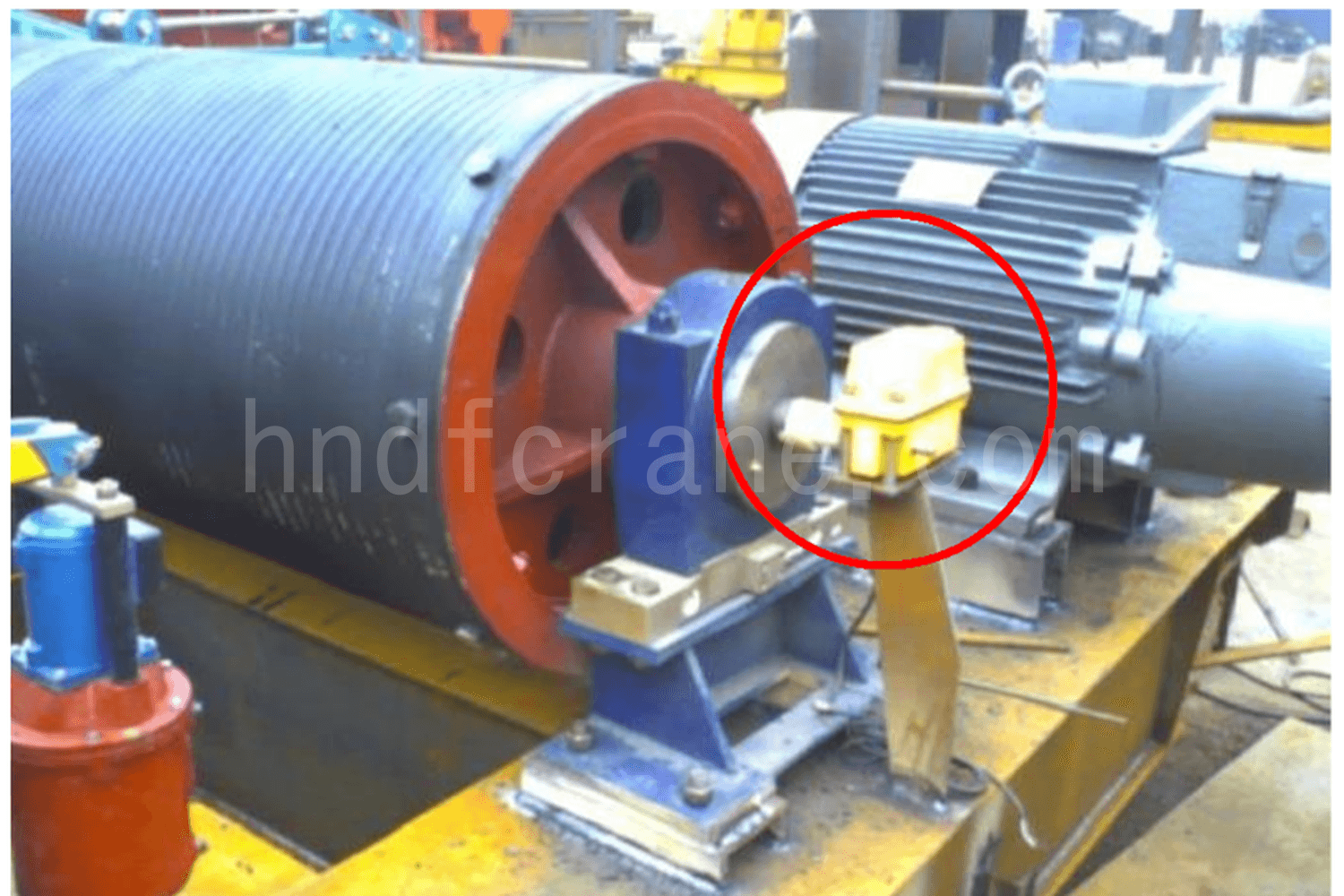
The limiter’s control range must be readjusted after the wire rope is replaced or its length changes.
2. Power Cut-Off Limit Switch
A power cut-off limit switch is connected in series with the hoist motor power circuit. Left or right movement of a drive rod actuates the switch, which then cuts off the main power circuit.
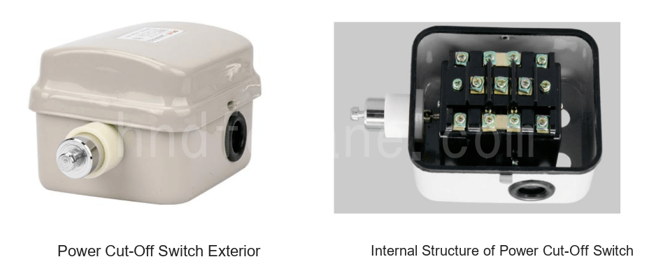
The drive rod is moved by a trigger block on the rope guide. During normal operation, the drive rod remains in its center position. When the hoisting mechanism reaches its upper or lower limit, the wire rope on the drum moves the rope guide to the left or right. The trigger block contacts the corresponding stop on the drive rod, moves the rod, and actuates the power cut-off switch to disconnect power to the hoist motor.
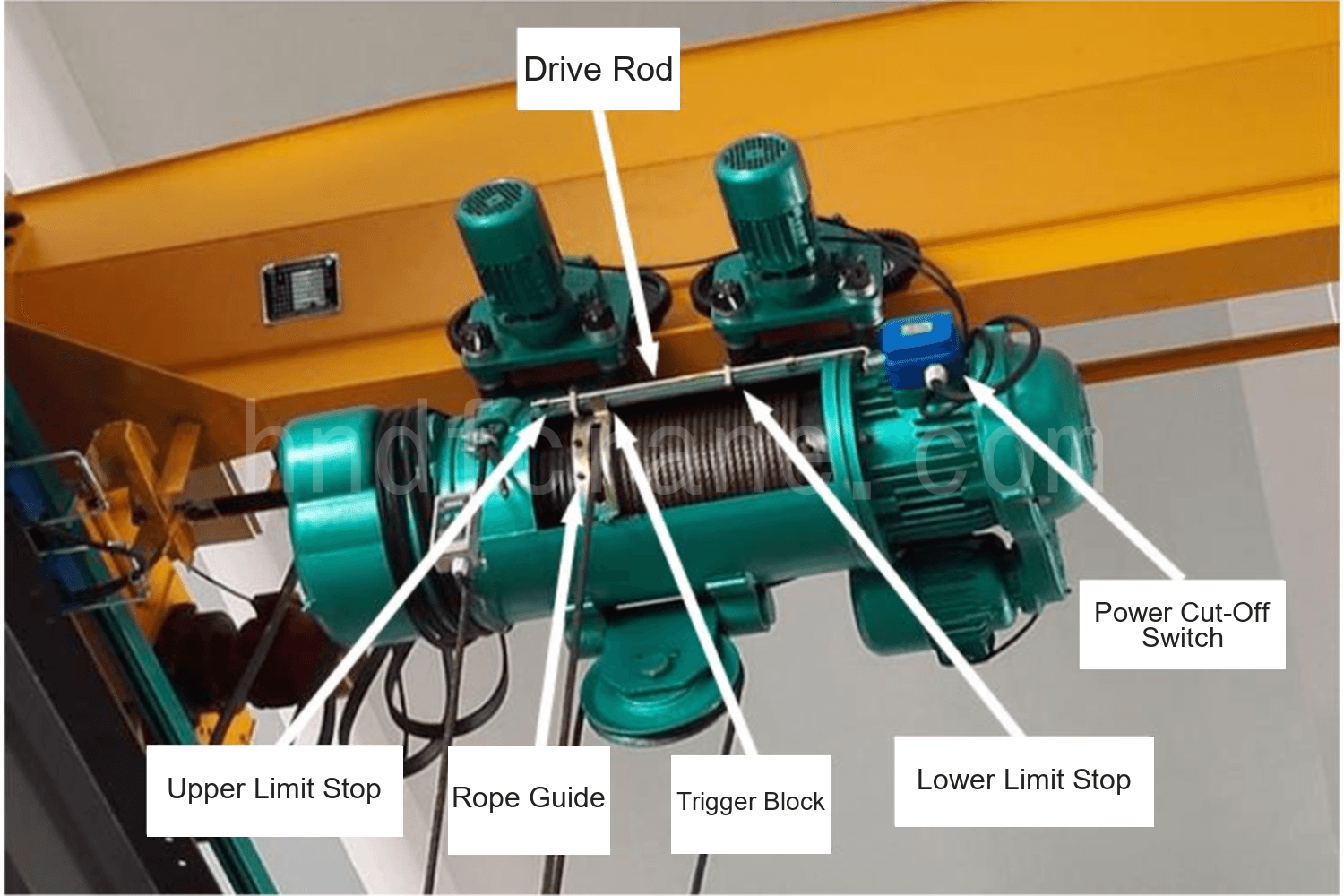
The switch is generally self-resetting. In its free state, the drive rod stays in the center and the switch remains closed. When the rod moves to either the left or right position, the switch opens.
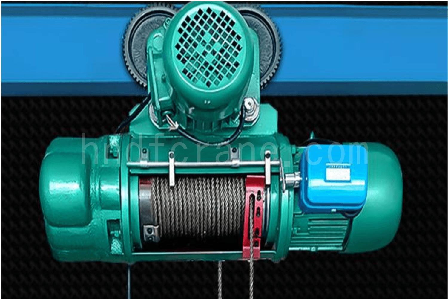
The fixed positions of the left and right stops on the drive rod determine when the switch is actuated. On an elektrikli tel halatlı vinç, the control range must also be readjusted after the wire rope is replaced or its length changes.
3. Heavy-Hammer Limit Switch
A heavy-hammer limit switch uses the interaction between a counterweight and a switch trigger rod to interrupt the hoisting control circuit. Its operation depends on the change in the counterweight position when it is lifted by the load-handling device.
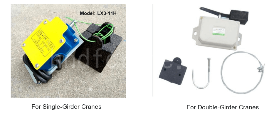
The limit switch is normally suspended below the crane trolley near the hoisting sheave block. The counterweight hangs from the switch trigger rod and fits loosely around the hoisting wire rope, allowing it to move freely up and down along the rope.
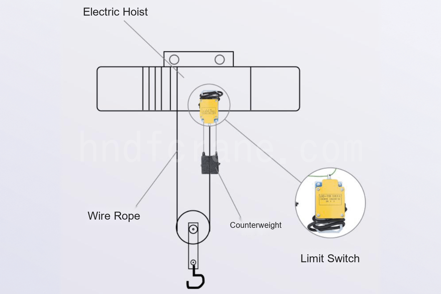
This limit switch is generally self-resetting:
- When the counterweight hangs freely from the trigger rod, the rod extends, the limit switch closes, and the hoisting mechanism can respond to a lifting command.
- When the hook or another load-handling device rises and contacts the counterweight, the counterweight moves upward along the wire rope. Its suspension rope becomes slack, the trigger rod retracts, the limit switch opens, and the hoisting control power is disconnected, stopping the upward motion.
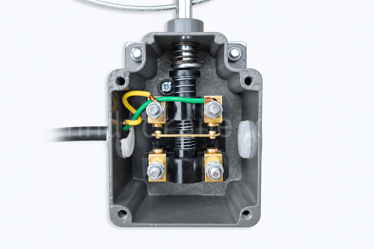
The upper lifting limit is controlled by the length of the counterweight suspension rope. Replacing the hoisting wire rope or changing its length does not affect this upper-limit setting.
4. Pressure-Plate Hoist Limit Switch
A pressure-plate hoist limit switch uses the linked movement of a counterweight and pressure plate to actuate the switch and interrupt the hoisting control circuit. It is mainly used on cranes whose lifting mechanism is an electric hoist.
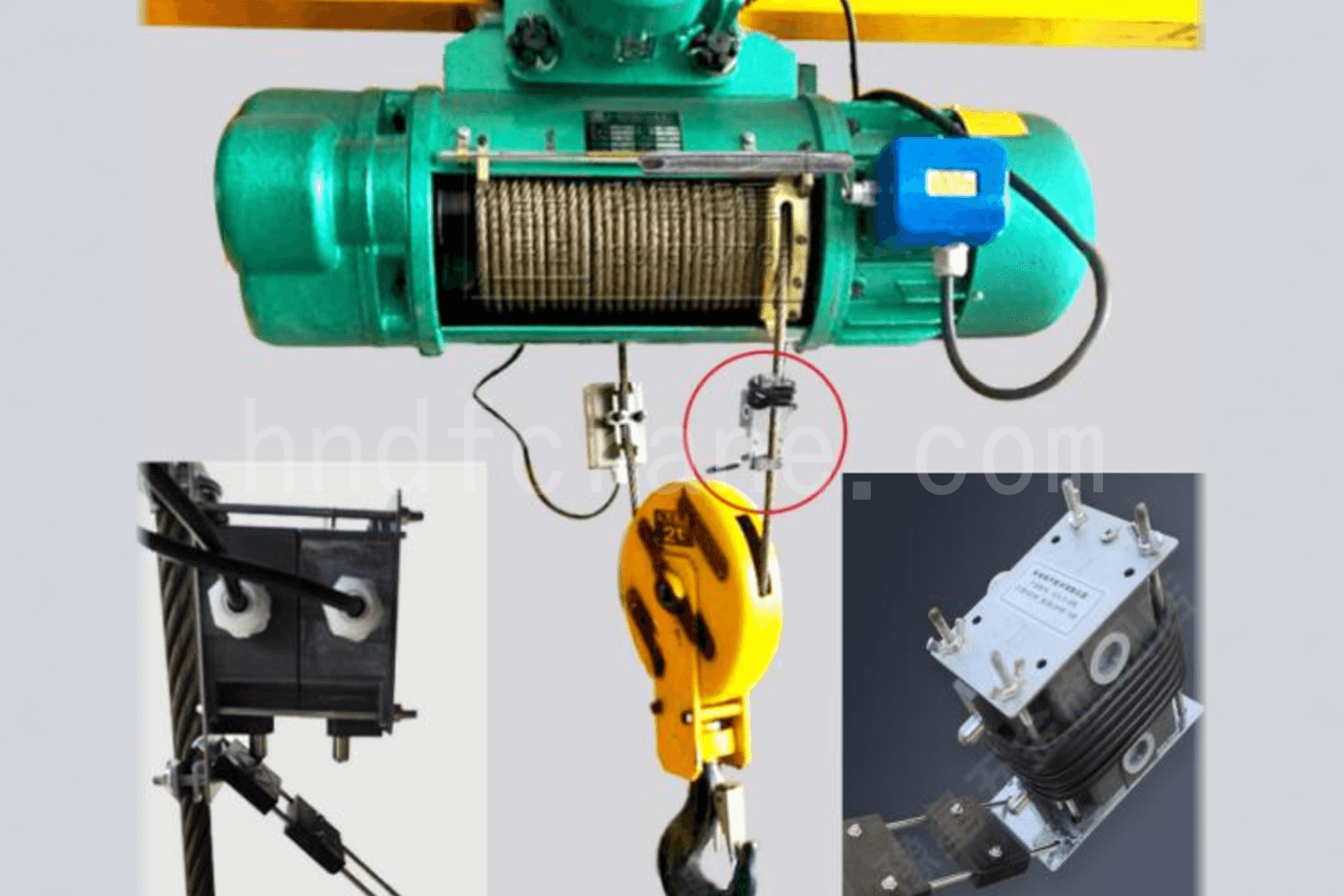
The switch is connected in series with the control circuit and is normally closed. It is installed at the upper-limit position of the electric-hoist wire rope with the pressure plate facing downward. When the rising hook block contacts the switch support plate, the lower contacts are actuated, changing the state of the crane’s main circuit or operating-speed circuit.
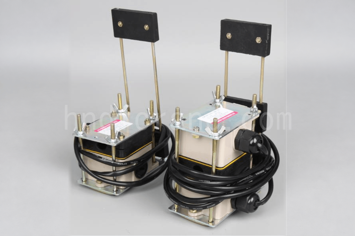
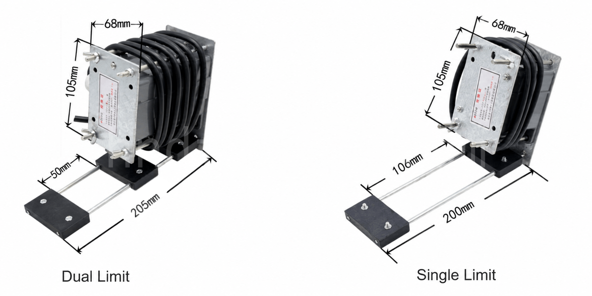
A single-limit switch is mainly used for height limiting and disconnecting the main-circuit power supply. A dual-limit switch adds a second height-limit stage to prevent an over-hoist event caused by a stuck contactor or failure of the first power cut-off stage. On a two-speed electric hoist, a dual-limit switch can also provide fast- and slow-speed limiting functions.
Adjustment Considerations for Overhead Crane Hoist Limit Switches
The four designs use different trigger methods, so their inspection and adjustment criteria also differ. For transmission and power cut-off devices, the trigger position is related to drum rotation, rope-guide travel, and wire-rope travel. Their control range must be readjusted after the rope is replaced or its length changes. The upper limit of a heavy-hammer device is mainly determined by the counterweight suspension-rope length. For a pressure-plate device, the operating relationship must be confirmed according to whether the mechanism uses a single-limit or dual-limit configuration.

Ben Cindy, vinç sektöründe 10 yıllık çalışma deneyimim ve çok sayıda profesyonel bilgi birikimim var. 500'den fazla müşteri için tatmin edici vinçleri seçtim. Vinçlerle ilgili herhangi bir ihtiyacınız veya sorunuz varsa lütfen benimle iletişime geçmekten çekinmeyin, uzmanlığımı ve pratik deneyimimi kullanarak sorunu çözmenize yardımcı olacağım!
Sorgunuzu Gönderin
- E-posta: satış@hndfcrane.com
- Naber: +86 191 3738 6654
- Telgraf: +86 191 3738 6654
- Tel: +86-373-581 8299
- Faks: +86-373-215 7000
- Adres: Changnao Sanayi Bölgesi, Xinxiang Şehri, Henan Eyaleti, Çin
 WeChat
- Gezer Vinçler
- Çift Kirişli Gezer Vinçler
- Tek Kirişli Gezer Vinçler
- Avrupa Tipi Tek Kirişli Köprülü Vinçler
- Patlama Korumalı Gezer Vinçler
- Kepçeli ve Manyetik Gezer Vinçler
- Monoray Vinçler
- Dökümhane Vinçleri
- İş İstasyonu Vinçleri: Modüler Kaldırma Çözümü
- Pergel Vinçler
- Duvara Monte Pergel Vinçler
- Duvar Gezmeli Pergel Vinçler
- Serbest Daimi Pergel Vinçler
- Alüminyum Jib Vinçler: Kolay Kaldırma için Hafif, Düzgün Dönen Kol
- Dengeli Jib Vinçler: Kısa Mesafeli Mekanik Montaj İçin Verimli Hafif Kaldırma
- Manuel Serbest Duran Jib Vinçler: Sınırlı Alan Operasyonları için Verimli Manuel Kaldırma Çözümleri
- Elektrikli Serbest Duran Bomlu Vinçler: Yüksek Kapasiteli Hızlı Kaldırma İçin Tamamen Elektrikli Çözüm
- Mafsallı Bomlu Vinçler: Çift Kollu Esneklik ile Hassas Kaldırma
- Portal Vinçler
- Çift Kiriş Portal Vinçler
- Yarı Portal Vinçler
- Tek Kiriş Portal Vinçler
- Truss Portal Vinçler
- Konteyner Portal Vinçler
- Ayarlanabilir Portal Vinçler
- Portatif Portal Vinçler
- Avrupa Portal Vinçler
- endüstriler
- Genel İmalat
- Atık İşleme
- Prekast
- Güç
- Taş
- kağıt yapımı
- metal üretimi
- Köprü İnşaatı
- Liman Vinçleri: Konteyner ve Toplu Malzeme Elleçleme İçin
- Petrol ve Gaz Endüstrisi için Köprülü Vinçler: Operasyonel Verimliliği Artırın
- Gemilerde Verimli Kargo Yüklemesi için Deniz Vinçleri
- Otomotiv Endüstrisi için Köprülü Vinçler: Verimli Otomasyon Çözümleri
- Elektrikli Vinçler
- Elektrikli Halatlı Vinçler
- Elektrikli Zincirli Vinçler
- Avrupa Tipi Elektrikli Vinçler
- Avrupa Elektrikli Zincirli Vinçler: Düzgün Çalışma, Düşük Gürültü ve Enerji Verimliliği
- Manuel Kaldıraçlı Vinçler: Çekme ve Kaldırma Görevleri İçin İdeal
- El Zincirli Vinçler: Güç Olmayan Alanlar İçin Manuel Kaldırma
- Düşük Tavan Elektrikli Vinçler: Maksimum Alan Verimliliği için Kompakt Tasarım
- Pnömatik Zincirli Vinçler: Endüstriyel Kullanım İçin Sorunsuz Kullanım
- Patlamaya Dayanıklı Manuel Zincirli Vinçler: Tehlikeli Alanlar İçin Kıvılcım Çıkarmayan Bakır Alaşımlı Yapı
- Tehlikeli Alanlarda Kaldırma İşlemleri İçin Patlamaya Dayanıklı Elektrikli Zincirli Vinçler
- Hakkında
- Vakalar
- Haberler
- SSS
- İndirmek
- Bloglar
- Çevrimiçi Vinç Tekerlek Yükü Hesaplama Araçları
- SG Panoraması
- Bize Ulaşın
- E-posta: satış@hndfcrane.com
- Naber: +86 191 3738 6654
- Telgraf: +86 191 3738 6654
- Tel: +86-373-581 8299
-