
-
Industrieën
-
Algemene productie
-
Afvalverwerking
-
Prefab
-
Stroom
-
Steen
-
Papier maken
-
Metaalproductie
-
Brug constructie
-
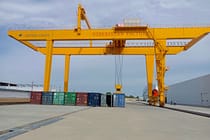
Havenkranen: voor het verwerken van containers en bulkmateriaal
-
Bovenloopkranen voor de petroleum- en gasindustrie: Verbeter de operationele efficiëntie
-
Maritieme kranen voor efficiënt laden van vracht op schepen
-
Bovenloopkranen voor de auto-industrie: efficiënte automatiseringsoplossingen
-
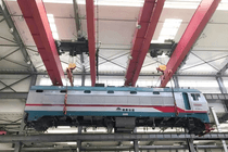
Bovenloopkraanoplossingen voor spoorwegen: spoor leggen, onderhoud van rollend materieel en containerafhandeling
-
Bovenloopkranen voor de voedings- en drankenindustrie: betrouwbare oplossingen voor efficiënte handling
-
Bovenloopkranen voor efficiënte cement-, glas-, baksteen- en prefab betonproductie
-
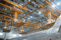
Bovenloopkranen voor de luchtvaartindustrie: vliegtuigonderhoud en -assemblage
-
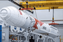
Luchtvaartbovenloopkranen: nauwkeurig hijsen voor raketlancering en -transport
-
-
Producten
-
Bovenloopkranen
-
Enkele ligger bovenloopkranen
-
Dubbelligger bovenloopkranen
-
Europese enkelligger bovenloopkranen
-
Europese type dubbelligger bovenloopkranen
-
Explosieveilige bovenloopkranen
-
Grijper en magnetische bovenloopkranen
-
Monorailkranen
-
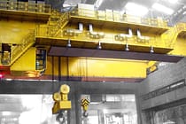
Gieterij Bovenloopkranen
-
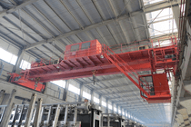
Isolatie Bovenloopkranen
-
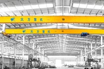
Bovenloopkranen met lage doorrijhoogte
-
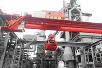
Grijp bovenloopkranen
-

Schep bovenloopkranen
-
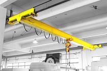
Ondergehangen bovenloopkranen
-
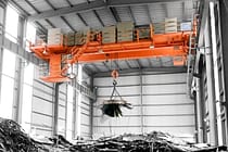
Elektromagnetische bovenloopkranen
-
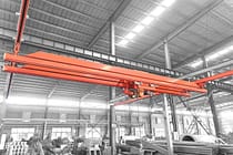
Werkstationkranen: modulaire hijsoplossing
-
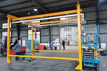
Vrijstaande werkstationbrugkranen
-
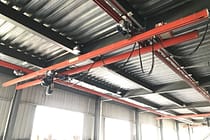
Plafondgemonteerde brugkraan
-
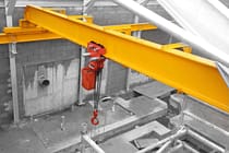
Handmatige bovenloopkranen
-
-
Portaalkranen
-
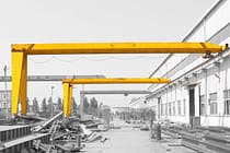
Semi-portaalkranen
-
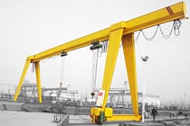
Enkelligger portaalkranen
-
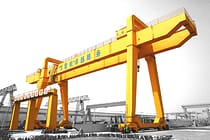
Dubbelligger portaalkranen
-
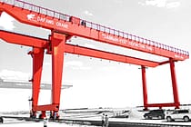
Portaalkranen voor containers
-
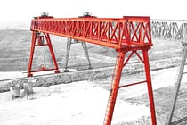
Truss-portaalkranen
-
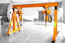
Verstelbare portaalkranen
-
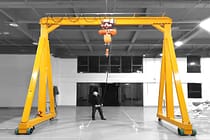
Draagbare portaalkranen
-
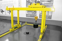
Europese portaalkranen
-
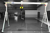
Aluminium portaalkranen
-
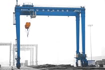
Container portaalkranen met rubberen banden
-
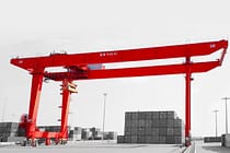
Rail gemonteerde container portaalkranen
-
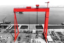
Scheepswerf portaalkraan
-
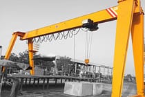
Europese portaalkranen met enkele ligger
-
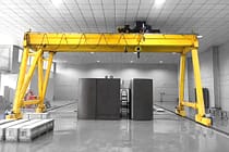
Europese dubbelligger portaalkranen
-
- Zwenkkranen
- Speciale kranen
- Elektrische takels
- Transferwagens
-
Bovenloopkranen
-
Kraan Onderdelen
-
Grijp emmers
-
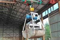
Elektrische roestvrijstalen grijperbak
-
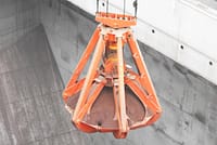
Mechanische vier-touws sinaasappelschillengrijpers
-
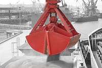
Mechanische vier-kabel grijper emmer
-
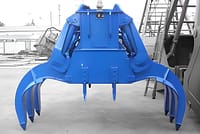
Elektrohydraulische rechthoekige grijpers
-
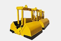
Elektrohydraulische grijpers
-
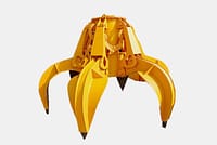
Elektrohydraulische sinaasappelschilgrijpers, hydraulische cactusgrijper
-
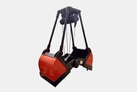
Elektrische motorgrijper
-
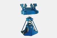
Elektrische monorailgrijper met monorailtakel
-
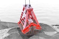
Afstandsbediening Clamshell-grijpers
-
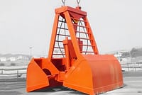
Mechanische twee-touwen grijpers
-
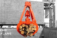
Houtgrijpers
-
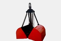
Enkele touwgrijper emmer
-
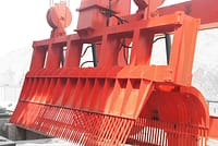
Afvalrekreinigingsmachines
-
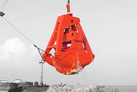
Baggergrijpers
-
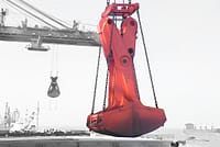
Trimgrijpers
-
- Kraan spreider
-
Kraan reserveonderdelen
-
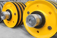
Kraanpoelies
-
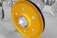
Staalkabel Schoven
-
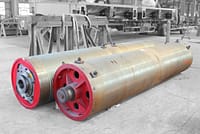
Kraankabeltrommel
-
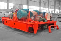
Kraanwagen
-
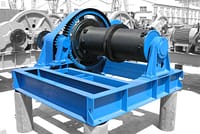
Elektrische lier
-
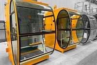
Cabine voor kraanmachinist
-
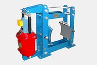
Bovenloopkraan remmen
-
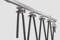
Kabels voor bovenloopkranen
-
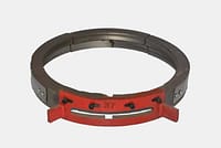
Kabelgeleiders voor bovenloopkranen
-
Bovenloopkraangeleiders en stroomtoevoerleidingen
-
Bovenloopkraanrails
-
Bovenloopkraan railklemmen
-
Bovenloopkraanmotoren
-
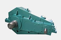
Bovenloopkraan-reductiekasten
-
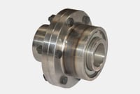
Koppelingen voor bovenloopkranen
-
- Kraanwielen
-
Grijp emmers
- Bedrijf
- Contact

-
Industrieën
-
Algemene productie
-
Afvalverwerking
-
Prefab
-
Stroom
-
Steen
-
Papier maken
-
Metaalproductie
-
Brug constructie
-
Havenkranen: voor het verwerken van containers en bulkmateriaal
-
Bovenloopkranen voor de petroleum- en gasindustrie: Verbeter de operationele efficiëntie
-
Maritieme kranen voor efficiënt laden van vracht op schepen
-
Bovenloopkranen voor de auto-industrie: efficiënte automatiseringsoplossingen
-
Bovenloopkraanoplossingen voor spoorwegen: spoor leggen, onderhoud van rollend materieel en containerafhandeling
-
Bovenloopkranen voor de voedings- en drankenindustrie: betrouwbare oplossingen voor efficiënte handling
-
Bovenloopkranen voor efficiënte cement-, glas-, baksteen- en prefab betonproductie
-
Bovenloopkranen voor de luchtvaartindustrie: vliegtuigonderhoud en -assemblage
-
Luchtvaartbovenloopkranen: nauwkeurig hijsen voor raketlancering en -transport
-
-
Producten
-
Bovenloopkranen
-
Enkele ligger bovenloopkranen
-
Dubbelligger bovenloopkranen
-
Europese enkelligger bovenloopkranen
-
Europese type dubbelligger bovenloopkranen
-
Explosieveilige bovenloopkranen
-
Grijper en magnetische bovenloopkranen
-
Monorailkranen
-
Gieterij Bovenloopkranen
-
Isolatie Bovenloopkranen
-
Bovenloopkranen met lage doorrijhoogte
-
Grijp bovenloopkranen
-
Schep bovenloopkranen
-
Ondergehangen bovenloopkranen
-
Elektromagnetische bovenloopkranen
-
Werkstationkranen: modulaire hijsoplossing
-
Vrijstaande werkstationbrugkranen
-
Plafondgemonteerde brugkraan
-
Handmatige bovenloopkranen
-
-
Portaalkranen
-
Semi-portaalkranen
-
Enkelligger portaalkranen
-
Dubbelligger portaalkranen
-
Portaalkranen voor containers
-
Truss-portaalkranen
-
Verstelbare portaalkranen
-
Draagbare portaalkranen
-
Europese portaalkranen
-
Aluminium portaalkranen
-
Container portaalkranen met rubberen banden
-
Rail gemonteerde container portaalkranen
-
Scheepswerf portaalkraan
-
Europese portaalkranen met enkele ligger
-
Europese dubbelligger portaalkranen
-
- Zwenkkranen
- Speciale kranen
- Elektrische takels
- Transferwagens
-
Bovenloopkranen
-
Kraan Onderdelen
-
Grijp emmers
-
Elektrische roestvrijstalen grijperbak
-
Mechanische vier-touws sinaasappelschillengrijpers
-
Mechanische vier-kabel grijper emmer
-
Elektrohydraulische rechthoekige grijpers
-
Elektrohydraulische grijpers
-
Elektrohydraulische sinaasappelschilgrijpers, hydraulische cactusgrijper
-
Elektrische motorgrijper
-
Elektrische monorailgrijper met monorailtakel
-
Afstandsbediening Clamshell-grijpers
-
Mechanische twee-touwen grijpers
-
Houtgrijpers
-
Enkele touwgrijper emmer
-
Afvalrekreinigingsmachines
-
Baggergrijpers
-
Trimgrijpers
-
- Kraan spreider
-
Kraan reserveonderdelen
-
Kraanpoelies
-
Staalkabel Schoven
-
Kraankabeltrommel
-
Kraanwagen
-
Elektrische lier
-
Cabine voor kraanmachinist
-
Bovenloopkraan remmen
-
Kabels voor bovenloopkranen
-
Kabelgeleiders voor bovenloopkranen
-
Bovenloopkraangeleiders en stroomtoevoerleidingen
-
Bovenloopkraanrails
-
Bovenloopkraan railklemmen
-
Bovenloopkraanmotoren
-
Bovenloopkraan-reductiekasten
-
Koppelingen voor bovenloopkranen
-
- Kraanwielen
-
Grijp emmers
- Bedrijf
- Contact



Overhead Crane Hoist Limit Switches: Four Types and How They Work
Inhoudsopgave
Overhead crane hoist limit switches restrict the upward travel of a hook or other load-handling device and prevent the hoisting mechanism from continuing beyond its upper position. Four types are widely used in the industry: transmission, power cut-off, heavy-hammer, and pressure-plate limit devices.
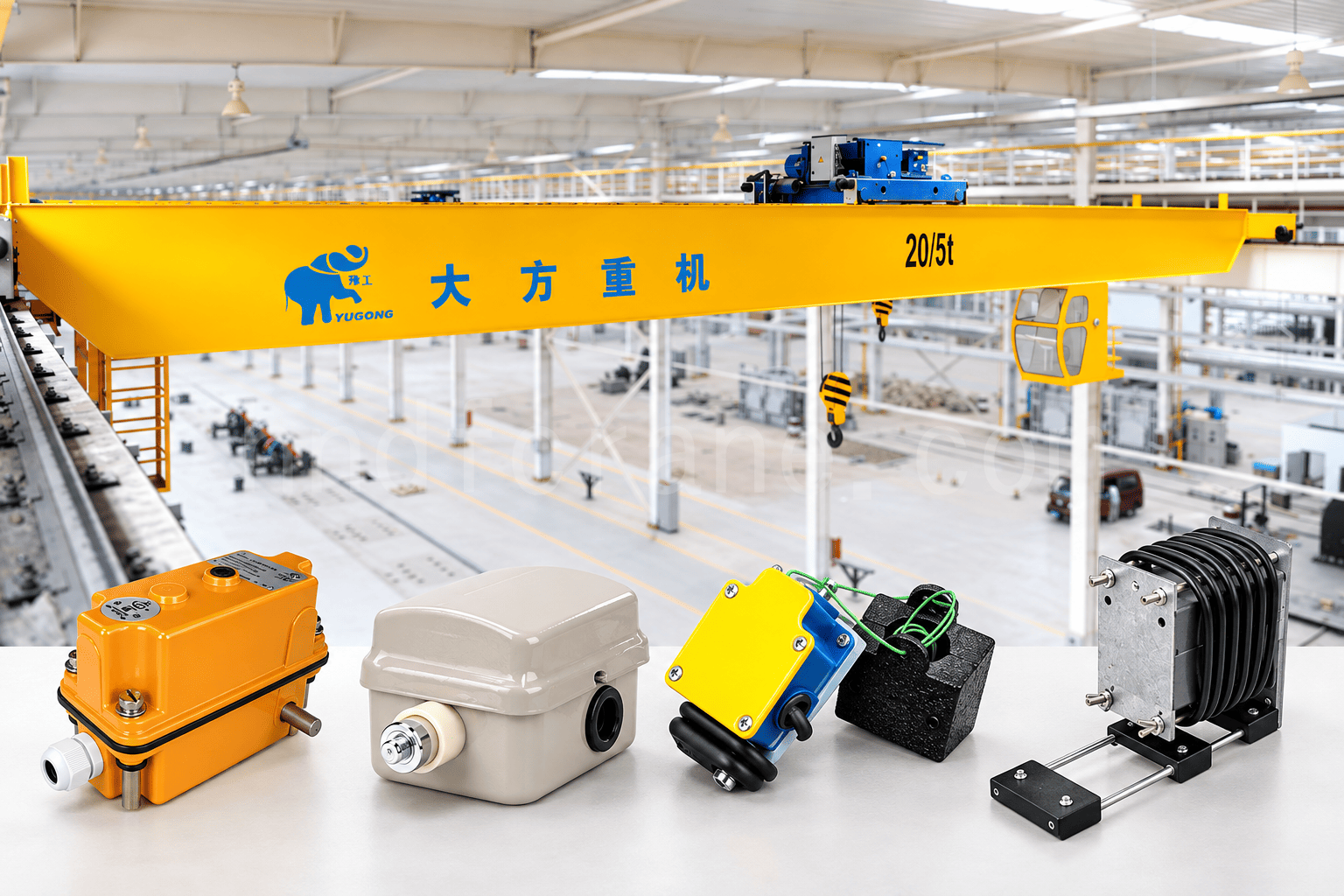
Comparison of Four Overhead Crane Hoist Limit Switches
| Type | Main Trigger Method | Typical Installation or Application | Adjustment Requirement |
|---|---|---|---|
| Transmission | The drum shaft drives a worm gearbox and cams that actuate limit switches | Tail end of the crane drum shaft | Readjust the control range after replacing the wire rope or changing its length |
| Power cut-off | A rope-guide trigger block moves the drive rod and actuates the power cut-off switch | Electric hoist lifting mechanism | Set the upper and lower limits through the left and right stop positions; readjust after a wire-rope change |
| Heavy-hammer | The hook or load-handling device lifts the counterweight, allowing the limit switch to reset and open | Below the trolley, near the hoisting sheave block | The counterweight suspension-rope length determines the upper lifting limit |
| Pressure-plate | The hook block contacts the pressure plate and moves the switch contacts | Cranes using an electric hoist | Available in single-limit and dual-limit configurations |
1. Transmission-Type Hoisting Height Limiter
A transmission-type hoisting height limiter uses a mechanical shaft drive to actuate a protective switch in the control circuit. Its operation depends on the mechanical linkage among the drum shaft, reduction mechanism, cams, and limit switches.
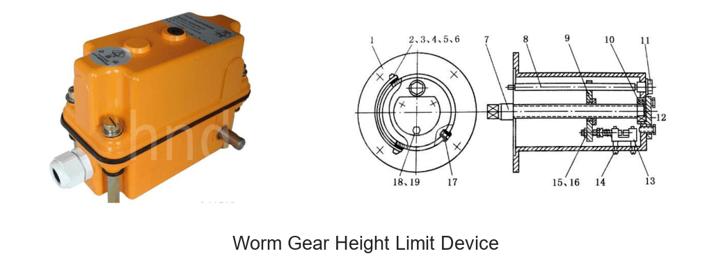
This device normally incorporates a worm gearbox with a high transmission ratio, so it is also known as a worm gear hoisting height limiter. It is generally installed at the tail end of the crane drum shaft. The drum shaft rotates the limiter’s worm, which turns the worm wheel and then the cams mounted on it. When a cam lobe contacts a limit switch, the switch controls the hoisting mechanism circuit and can cut off power to the mechanism.
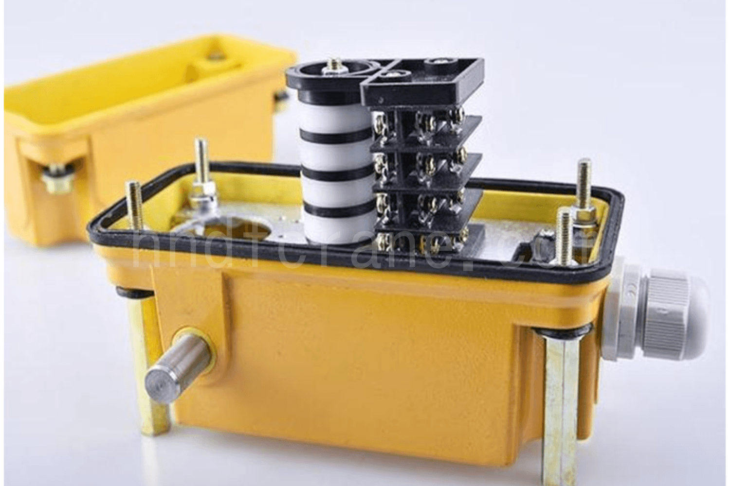
The device generally contains four cams and four limit switches. The cam lobes are staggered, which is why the device is also called a geared cam type. The four switches control:
- Deceleration before the upward travel approaches its limit.
- Stopping when the upward travel reaches its limit.
- Deceleration before the downward travel approaches its limit.
- Stopping when the downward travel reaches its limit.
Changing the positions of the cam lobes changes the actuation timing of the switches and therefore controls the lifting height and lowering depth.
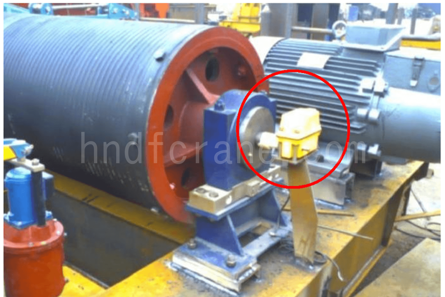
The limiter’s control range must be readjusted after the wire rope is replaced or its length changes.
2. Power Cut-Off Limit Switch
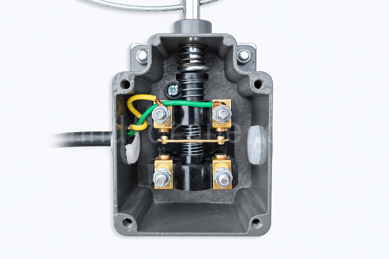
A power cut-off limit switch is connected in series with the hoist motor power circuit. Left or right movement of a drive rod actuates the switch, which then cuts off the main power circuit.
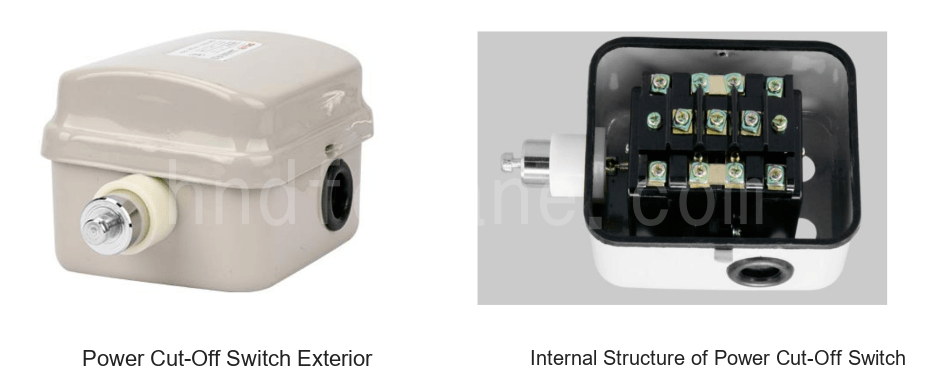
The drive rod is moved by a trigger block on the rope guide. During normal operation, the drive rod remains in its center position. When the hoisting mechanism reaches its upper or lower limit, the wire rope on the drum moves the rope guide to the left or right. The trigger block contacts the corresponding stop on the drive rod, moves the rod, and actuates the power cut-off switch to disconnect power to the hoist motor.
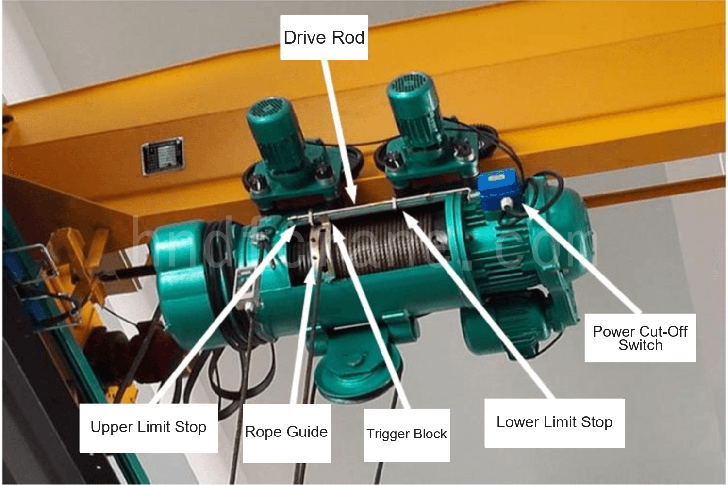
The switch is generally self-resetting. In its free state, the drive rod stays in the center and the switch remains closed. When the rod moves to either the left or right position, the switch opens.
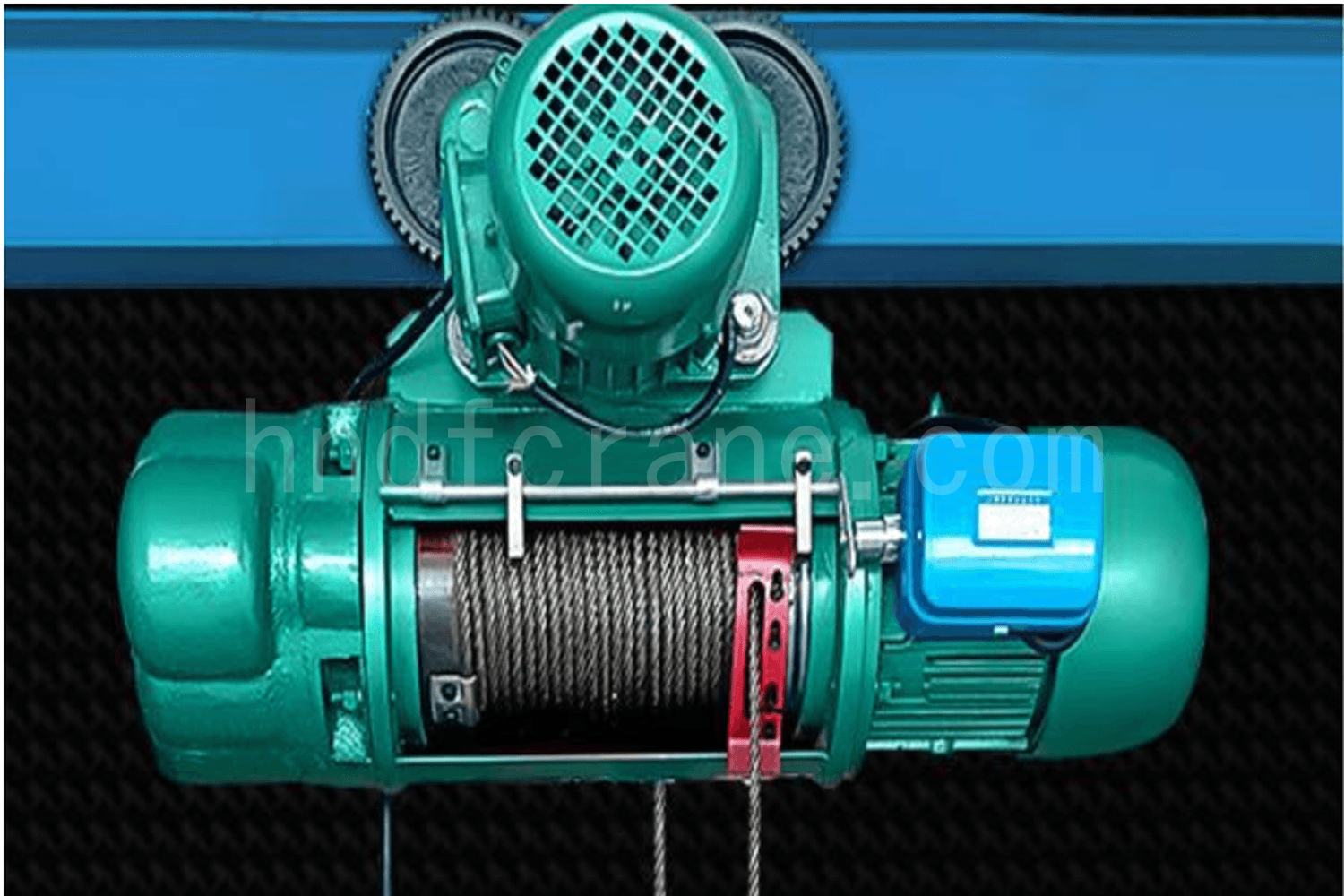
The fixed positions of the left and right stops on the drive rod determine when the switch is actuated. On an elektrische staaldraadtakel, the control range must also be readjusted after the wire rope is replaced or its length changes.
3. Heavy-Hammer Limit Switch
A heavy-hammer limit switch uses the interaction between a counterweight and a switch trigger rod to interrupt the hoisting control circuit. Its operation depends on the change in the counterweight position when it is lifted by the load-handling device.
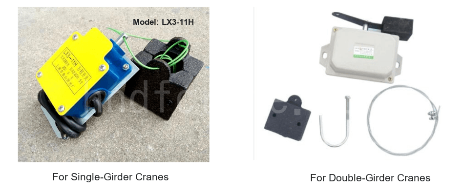
The limit switch is normally suspended below the crane trolley near the hoisting sheave block. The counterweight hangs from the switch trigger rod and fits loosely around the hoisting wire rope, allowing it to move freely up and down along the rope.
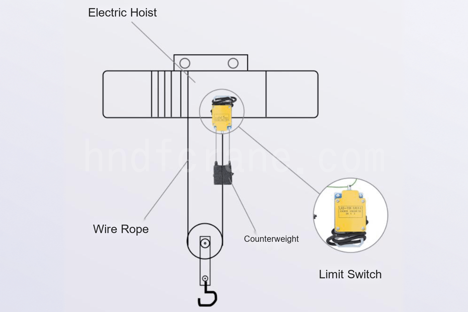
This limit switch is generally self-resetting:
- When the counterweight hangs freely from the trigger rod, the rod extends, the limit switch closes, and the hoisting mechanism can respond to a lifting command.
- When the hook or another load-handling device rises and contacts the counterweight, the counterweight moves upward along the wire rope. Its suspension rope becomes slack, the trigger rod retracts, the limit switch opens, and the hoisting control power is disconnected, stopping the upward motion.
The upper lifting limit is controlled by the length of the counterweight suspension rope. Replacing the hoisting wire rope or changing its length does not affect this upper-limit setting.
4. Pressure-Plate Hoist Limit Switch
A pressure-plate hoist limit switch uses the linked movement of a counterweight and pressure plate to actuate the switch and interrupt the hoisting control circuit. It is mainly used on cranes whose lifting mechanism is an electric hoist.
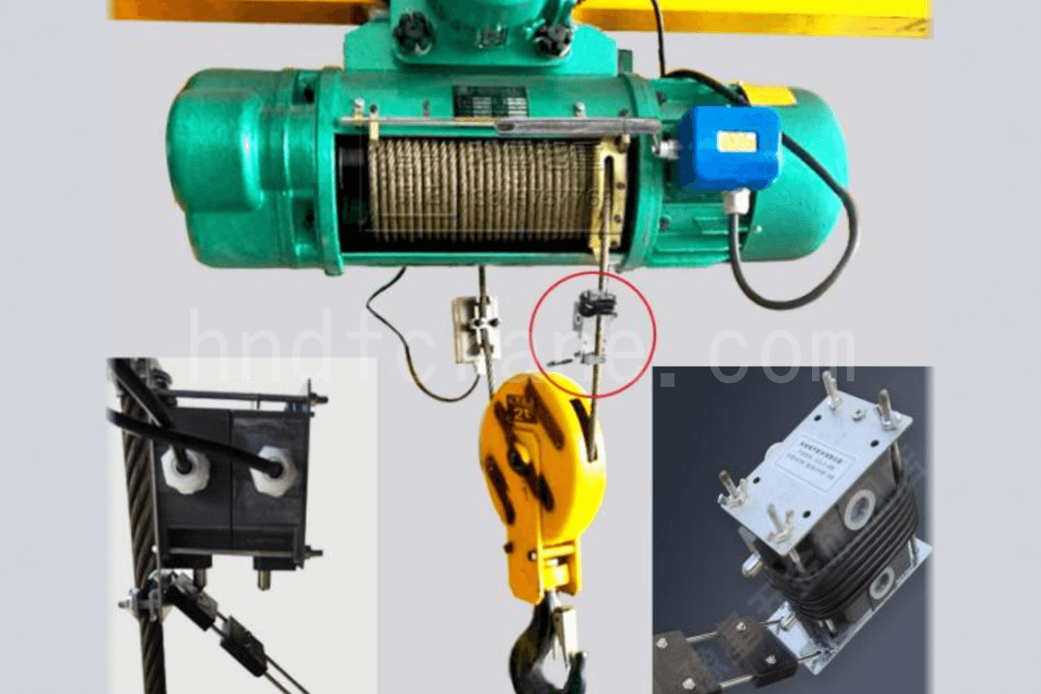
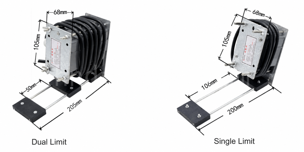
The switch is connected in series with the control circuit and is normally closed. It is installed at the upper-limit position of the electric-hoist wire rope with the pressure plate facing downward. When the rising hook block contacts the switch support plate, the lower contacts are actuated, changing the state of the crane’s main circuit or operating-speed circuit.
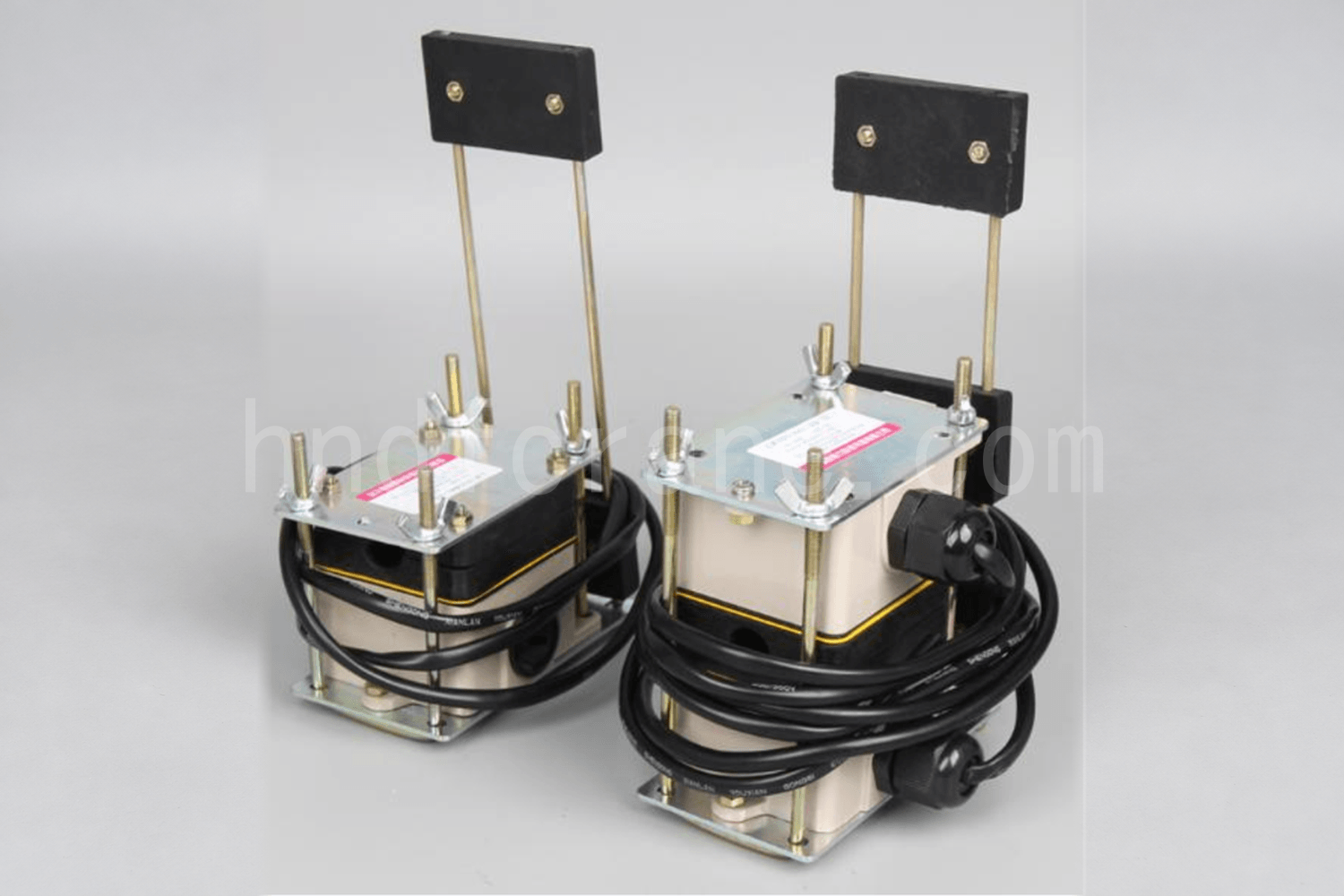
A single-limit switch is mainly used for height limiting and disconnecting the main-circuit power supply. A dual-limit switch adds a second height-limit stage to prevent an over-hoist event caused by a stuck contactor or failure of the first power cut-off stage. On a two-speed electric hoist, a dual-limit switch can also provide fast- and slow-speed limiting functions.
Adjustment Considerations for Overhead Crane Hoist Limit Switches
The four designs use different trigger methods, so their inspection and adjustment criteria also differ. For transmission and power cut-off devices, the trigger position is related to drum rotation, rope-guide travel, and wire-rope travel. Their control range must be readjusted after the rope is replaced or its length changes. The upper limit of a heavy-hammer device is mainly determined by the counterweight suspension-rope length. For a pressure-plate device, the operating relationship must be confirmed according to whether the mechanism uses a single-limit or dual-limit configuration.

Ik ben Cindy, met 10 jaar werkervaring in de kraanindustrie en een schat aan professionele kennis. Ik heb de bevredigende kranen voor meer dan 500 klanten geselecteerd. Als u behoeften of vragen over kranen hebt, neem dan gerust contact met mij op, ik zal mijn expertise en praktische ervaring gebruiken om u te helpen het probleem op te lossen!
Stuur uw aanvraag
- E-mail: sales@hndfcrane.com
- Whatsappen: +86 191 3738 6654
- Telegram: +86 191 3738 6654
- Tel: +86-373-581 8299
- Fax: +86-373-215 7000
- Toevoegen: Changnao Industrial District, Xinxiang City, provincie Henan, China
 WeChat
- Bovenloopkranen
- Dubbelligger bovenloopkranen
- Enkele ligger bovenloopkranen
- Europese enkelligger bovenloopkranen
- Explosieveilige bovenloopkranen
- Grijper en magnetische bovenloopkranen
- Monorailkranen
- Gieterij Bovenloopkranen
- Werkstationkranen: modulaire hijsoplossing
- Zwenkkranen
- Wandgemonteerde zwenkkranen
- Wandreizende kraanbalkkranen
- Vrijstaande zwenkkranen
- Aluminium giekkranen: lichtgewicht, soepel draaiende arm voor eenvoudig hijsen
- Balansjibkranen: efficiënt licht hijsen voor mechanische montage over korte afstanden
- Handmatige vrijstaande jibkranen: efficiënte handmatige hefoplossingen voor werkzaamheden in beperkte ruimte
- Elektrische vrijstaande zwenkkranen: een volledig elektrische oplossing voor snel hijsen met hoge capaciteit.
- Knikarmkranen: Nauwkeurig hijsen met de flexibiliteit van een dubbele arm
- Portaalkranen
- Dubbelligger portaalkranen
- Semi-portaalkranen
- Enkelligger portaalkranen
- Truss-portaalkranen
- Portaalkranen voor containers
- Verstelbare portaalkranen
- Draagbare portaalkranen
- Europese portaalkranen
- Industrieën
- Algemene productie
- Afvalverwerking
- Prefab
- Stroom
- Steen
- Papier maken
- Metaalproductie
- Brug constructie
- Havenkranen: voor het verwerken van containers en bulkmateriaal
- Bovenloopkranen voor de petroleum- en gasindustrie: Verbeter de operationele efficiëntie
- Maritieme kranen voor efficiënt laden van vracht op schepen
- Bovenloopkranen voor de auto-industrie: efficiënte automatiseringsoplossingen
- Elektrische takels
- Elektrische staaldraadtakels
- Elektrische kettingtakels
- Elektrische takels van het Europese type
- Europese elektrische kettingtakels: soepele werking, laag geluidsniveau en energiezuinigheid
- Handmatige heftrucks: ideaal voor trek- en tilwerkzaamheden
- Handkettingtakels: handmatig tillen voor gebieden zonder stroom
- Elektrische takels met lage hoofdruimte: compact ontwerp voor maximale ruimte-efficiëntie
- Pneumatische kettingtakels: soepele bediening voor industrieel gebruik
- Explosieveilige handtakels met ketting: vonkbestendige constructie van koperlegering voor gevaarlijke omgevingen.
- Explosieveilige elektrische kettingtakels voor hijswerkzaamheden in gevaarlijke omgevingen
- Over
- Gevallen
- Nieuws
- Veelgestelde vragen
- Downloaden
- Blogs
- Online hulpmiddelen voor het berekenen van de kraanwiellast
- VR-panorama
- Neem contact met ons op
- E-mail: sales@hndfcrane.com
- Whatsappen: +86 191 3738 6654
- Telegram: +86 191 3738 6654
- Tel: +86-373-581 8299
-