-
Отрасли
-
Общее производство
-
Обращение с отходами
-
сборный
-
Власть
-
Камень
-
Изготовление бумаги
-
Производство металла
-
Строительство моста
-
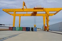
Портовые краны: для обработки контейнеров и сыпучих материалов
-

Мостовые краны для нефтяной и газовой промышленности: повышение эффективности работы
-

Морские краны для эффективной погрузки грузов на суда
-

Мостовые краны для автомобильной промышленности: эффективные решения по автоматизации
-
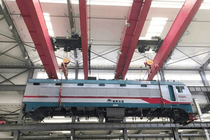
Решения с использованием мостовых кранов для железных дорог: укладка путей, техническое обслуживание подвижного состава и обработка контейнеров
-

Мостовые краны для продуктов питания и напитков: надежные решения для эффективной обработки грузов
-
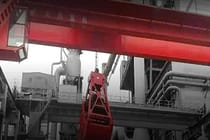
Мостовые краны для эффективного производства цемента, стекла, кирпича и сборного бетона
-
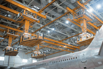
Мостовые краны для авиационной промышленности: техническое обслуживание и сборка самолетов
-
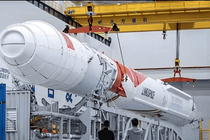
Мостовые краны для аэрокосмической промышленности: точный подъем грузов для запуска и транспортировки ракет
-
-
Продукты
-
Мостовой Кран
-
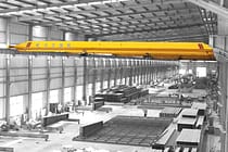
Кран Мостовой Однобалочный
-
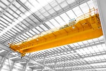
Кран Мостовой Двухбалочный
-
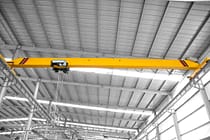
Однобалочные мостовые краны европейского типа
-
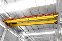
Двухбалочные мостовые краны европейского типа
-
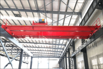
Взрывозащищенные Мостовые Краны
-
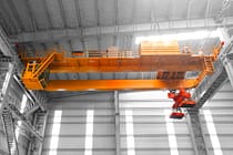
Грейферные и магнитные мостовые краны
-
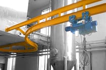
Монорельсовые краны
-
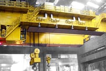
Литейные Мостовые Краны
-
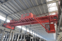
Изоляция мостовых кранов
-
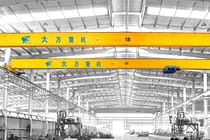
Мостовые краны с низкой габаритной высотой
-
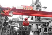
Грейферные мостовые краны
-
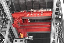
Ковшовые мостовые краны
-
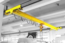
Подвесные мостовые краны
-
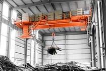
Электромагнитные мостовые краны
-
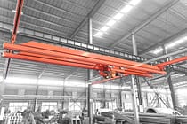
Рабочие краны: легкая конструкция, простой монтаж и удобство в эксплуатации.
-
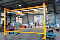
Отдельно стоящие рабочие станции мостовые краны
-
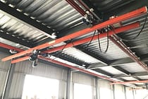
Мостовой кран, монтируемый на потолке
-
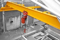
Ручные мостовые краны
-
-
Козловой Кран
-
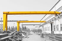
Полукозловой Кран
-
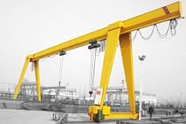
Однобалочный Козловой Кран
-
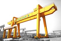
Двухбалочный Козловой Кран
-
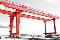
Kозловой Kонтейнерный Kран
-
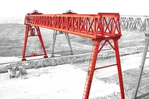
Козловые Краны С Фермами
-
Регулируемые козловые краны
-
Mини Kозловой Kран
-
Европейские Козловые Краны
-

Алюминиевые козловые краны
-
Контейнерные козловые краны на резиновых шинах
-
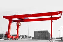
Контейнерные козловые краны на рельсовом ходу
-
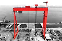
Козловой кран для судостроительной верфи
-
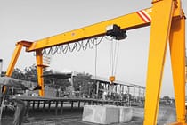
Европейские однобалочные козловые краны
-
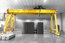
Европейские двухбалочные козловые краны
-
-
Консольный Кран
-
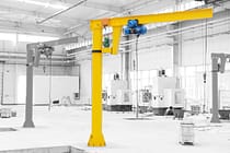
Kран Kонсольный Hа Kолонне
-
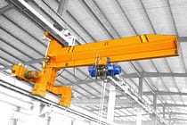
Настенно-Передвижной Консольный Кран
-
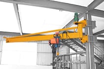
Кран Консульный Настенный
-
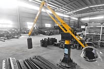
Балансировочные поворотные краны
-
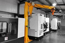
Электрические отдельно стоящие поворотные краны
-
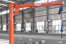
Ручные отдельно стоящие консольные краны
-
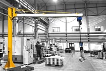
Алюминиевые консольные краны
-
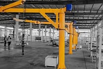
Шарнирно-сочлененные краны
-
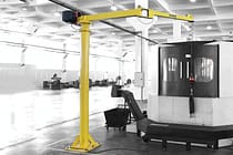
Умные поворотные краны
-
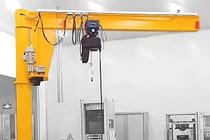
Стандартные поворотные краны FEM
-
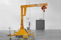
Переносные поворотные краны
-
-
Специальные краны
-
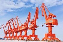
Портальные краны для гавани
-
Краны для чистых помещений
-
Мобильные лодочные подъемники
-
Козловой кран со щитом для проходки тоннелей
-
Портальные перевозчики
-

Система обработки сегментов
-
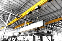
Оцинковка блокировочных кранов
-
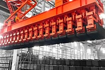
Кран для штабелирования блоков анода из углеродного волокна
-
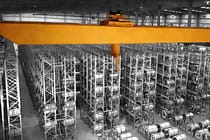
Штабелерный кран
-
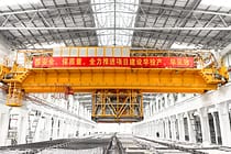
Электролитический медный мостовой кран
-
- Tельфер Электрический
- Тележки для переноса
-
Мостовой Кран
-
Запчасти для кранов
-
Ковши для сбора мусора
-
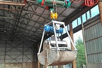
Электрический грейферный ковш из нержавеющей стали
-
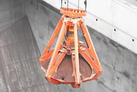
Механические четырехканатные грейферы Orange Peel
-
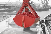
Механический четырехканатный грейферный ковш
-
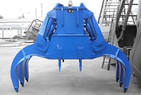
Электрогидравлические прямоугольные грейферы
-
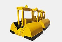
Электрогидравлические грейферные захваты
-
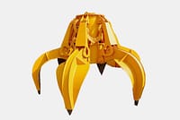
Электрогидравлические грейферы Orange Peel, Гидравлический грейфер Cactus
-
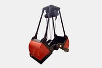
Грейфер с электродвигателем
-
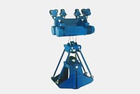
Электрический монорельсовый грейферный ковш с монорельсовым подъемником
-
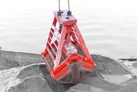
Грейферы с дистанционным управлением
-
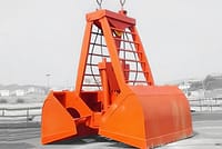
Механические двухканатные грейферы
-
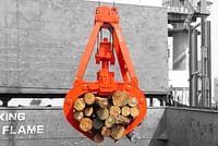
Лесозаготовительные грейферы
-
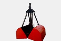
Грейферный ковш с одним тросом
-
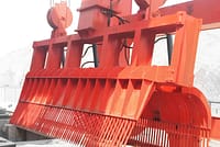
Машины для очистки мусорных корзин
-
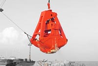
Грейферы для дноуглубительных работ
-
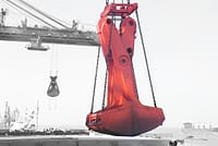
Обрезка захватов
-
- Кран-распределитель
-
Запасные части для кранов
-
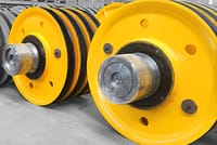
Блоки крана
-
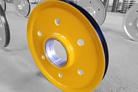
Канатные шкивы
-
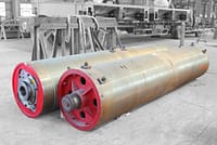
Кран канатный барабан
-
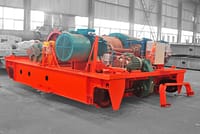
Крановая тележка
-
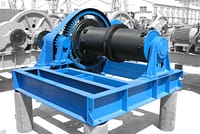
Электрическая лебедка
-
Кабина крановщика
-
Тормоза мостового крана
-
Кабели мостового крана
-
Направляющие каната мостового крана
-
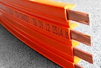
Провода мостовых кранов и линии электропередач
-
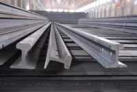
Рельсы мостового крана
-
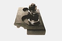
Зажимы для рельс мостового крана
-
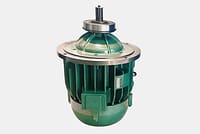
Двигатели мостовых кранов
-
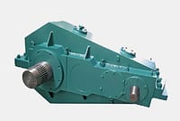
Редукторы мостовых кранов
-
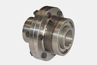
Муфты для мостового крана
-
- Kрановое Kолесо
-
Ковши для сбора мусора
- Компания
- Контакт

-
Отрасли
-
Общее производство
-
Обращение с отходами
-
сборный
-
Власть
-
Камень
-
Изготовление бумаги
-
Производство металла
-
Строительство моста
-
Портовые краны: для обработки контейнеров и сыпучих материалов
-
Мостовые краны для нефтяной и газовой промышленности: повышение эффективности работы
-
Морские краны для эффективной погрузки грузов на суда
-
Мостовые краны для автомобильной промышленности: эффективные решения по автоматизации
-
Решения с использованием мостовых кранов для железных дорог: укладка путей, техническое обслуживание подвижного состава и обработка контейнеров
-
Мостовые краны для продуктов питания и напитков: надежные решения для эффективной обработки грузов
-
Мостовые краны для эффективного производства цемента, стекла, кирпича и сборного бетона
-
Мостовые краны для авиационной промышленности: техническое обслуживание и сборка самолетов
-
Мостовые краны для аэрокосмической промышленности: точный подъем грузов для запуска и транспортировки ракет
-
-
Продукты
-
Мостовой Кран
-
Кран Мостовой Однобалочный
-
Кран Мостовой Двухбалочный
-
Однобалочные мостовые краны европейского типа
-
Двухбалочные мостовые краны европейского типа
-
Взрывозащищенные Мостовые Краны
-
Грейферные и магнитные мостовые краны
-
Монорельсовые краны
-
Литейные Мостовые Краны
-
Изоляция мостовых кранов
-
Мостовые краны с низкой габаритной высотой
-
Грейферные мостовые краны
-
Ковшовые мостовые краны
-
Подвесные мостовые краны
-
Электромагнитные мостовые краны
-
Рабочие краны: легкая конструкция, простой монтаж и удобство в эксплуатации.
-
Отдельно стоящие рабочие станции мостовые краны
-
Мостовой кран, монтируемый на потолке
-
Ручные мостовые краны
-
-
Козловой Кран
-
Полукозловой Кран
-
Однобалочный Козловой Кран
-
Двухбалочный Козловой Кран
-
Kозловой Kонтейнерный Kран
-
Козловые Краны С Фермами
-
Регулируемые козловые краны
-
Mини Kозловой Kран
-
Европейские Козловые Краны
-
Алюминиевые козловые краны
-
Контейнерные козловые краны на резиновых шинах
-
Контейнерные козловые краны на рельсовом ходу
-
Козловой кран для судостроительной верфи
-
Европейские однобалочные козловые краны
-
Европейские двухбалочные козловые краны
-
-
Консольный Кран
-
Kран Kонсольный Hа Kолонне
-
Настенно-Передвижной Консольный Кран
-
Кран Консульный Настенный
-
Балансировочные поворотные краны
-
Электрические отдельно стоящие поворотные краны
-
Ручные отдельно стоящие консольные краны
-
Алюминиевые консольные краны
-
Шарнирно-сочлененные краны
-
Умные поворотные краны
-
Стандартные поворотные краны FEM
-
Переносные поворотные краны
-
-
Специальные краны
-
Портальные краны для гавани
-
Краны для чистых помещений
-
Мобильные лодочные подъемники
-
Козловой кран со щитом для проходки тоннелей
-
Портальные перевозчики
-
Система обработки сегментов
-
Оцинковка блокировочных кранов
-
Кран для штабелирования блоков анода из углеродного волокна
-
Штабелерный кран
-
Электролитический медный мостовой кран
-
- Tельфер Электрический
- Тележки для переноса
-
Мостовой Кран
-
Запчасти для кранов
-
Ковши для сбора мусора
-
Электрический грейферный ковш из нержавеющей стали
-
Механические четырехканатные грейферы Orange Peel
-
Механический четырехканатный грейферный ковш
-
Электрогидравлические прямоугольные грейферы
-
Электрогидравлические грейферные захваты
-
Электрогидравлические грейферы Orange Peel, Гидравлический грейфер Cactus
-
Грейфер с электродвигателем
-
Электрический монорельсовый грейферный ковш с монорельсовым подъемником
-
Грейферы с дистанционным управлением
-
Механические двухканатные грейферы
-
Лесозаготовительные грейферы
-
Грейферный ковш с одним тросом
-
Машины для очистки мусорных корзин
-
Грейферы для дноуглубительных работ
-
Обрезка захватов
-
- Кран-распределитель
-
Запасные части для кранов
-
Блоки крана
-
Канатные шкивы
-
Кран канатный барабан
-
Крановая тележка
-
Электрическая лебедка
-
Кабина крановщика
-
Тормоза мостового крана
-
Кабели мостового крана
-
Направляющие каната мостового крана
-
Провода мостовых кранов и линии электропередач
-
Рельсы мостового крана
-
Зажимы для рельс мостового крана
-
Двигатели мостовых кранов
-
Редукторы мостовых кранов
-
Муфты для мостового крана
-
- Kрановое Kолесо
-
Ковши для сбора мусора
- Компания
- Контакт



Crane Hoist Wire Rope Fatigue: Causes, Prevention, and Inspection
Оглавление
Why does crane hoist wire rope fatigue occur even without obvious overloading? During repeated lifting and lowering, wire ropes bend around drums and sheaves under tension, allowing small defects to develop into fatigue cracks and eventually cause broken wires. Inadequate lubrication, improper sheave sizing, and uneven spooling can accelerate this process. Understanding the causes, prevention measures, and testing methods is essential to managing fatigue risks and maintaining safe crane operation.
What Is Crane Hoist Wire Rope Fatigue Breakage?
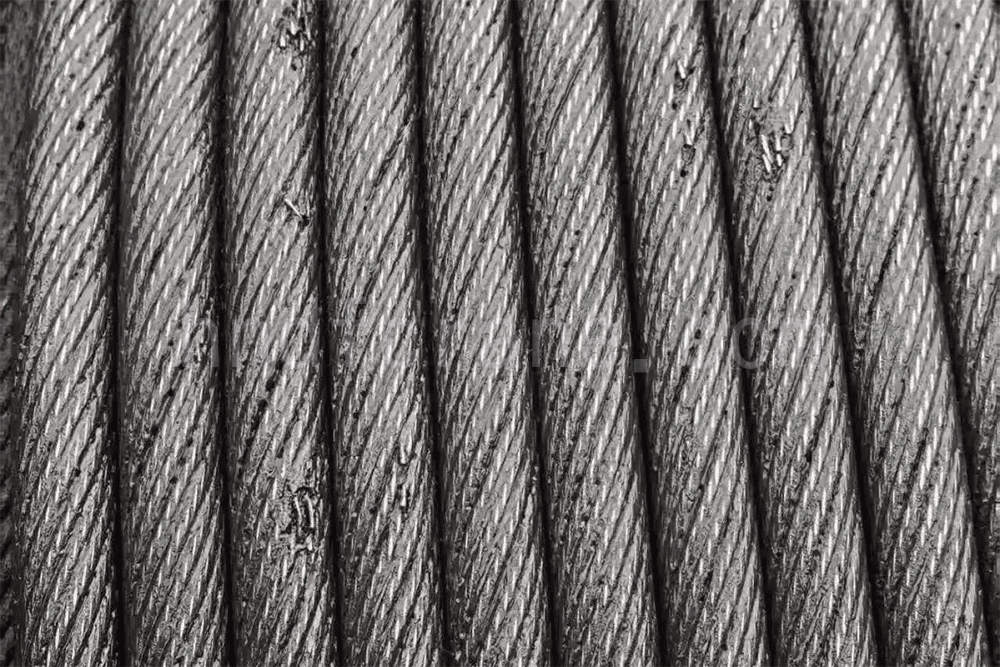
Crane hoist wire rope fatigue develops during repeated winding and unwinding on a hoist drum and sheaves. The wires are continuously exposed to alternating stresses caused by tension, bending, and compression. When repeated stress exceeds the fatigue resistance of the wire material, small fatigue cracks form on the wire surface. As operating cycles continue, the cracks grow inward and eventually cause wire breakage.
Fatigue breaks commonly have relatively flat fracture surfaces and usually show no obvious necking or plastic deformation. Broken wires are often concentrated where the rope contacts and carries load over a sheave or drum, and the breaks may appear in a regular distribution. This differs from the cup-shaped plastic fracture of an overload break and the sharp abrasive fracture associated with wear.
Main Causes of Fatigue Breaks in Crane Hoist Wire Rope
1. Alternating Bending Stress
Every time the wire rope passes over a барабан каната крана или crane sheave, the wires experience another forward or reverse bend. Reverse bending generally has a greater effect on rope fatigue life than bending in the same direction. When the ratio of drum or sheave diameter to rope diameter, D/d, is too small, the bending curvature increases, local stress concentration becomes more severe, and fatigue life can be significantly shortened. Frequent lifting and lowering allow small cracks to accumulate under cyclic loading.
2. Internal Fretting Wear
When the rope is loaded, small relative movements occur between strands and between individual wires. This produces fretting wear. Stress concentrations and small pits can form on the wire surface, creating sites where fatigue cracks may initiate. Lack of lubrication or dried-out grease accelerates internal wear and reduces fatigue life.
3. Impact Loads and Variable-Amplitude Stress
Sudden lifting or lowering, emergency braking, side pulling, and braking impacts can create short-duration additional dynamic loads. Every start and stop changes the actual rope tension and produces variable-amplitude fatigue stress, accelerating crack growth.
4. Drum and Sheave Condition Problems
Worn or unevenly worn sheave grooves, deformed grooves, poor rope spooling, crossed or disordered wraps, and crushing in multilayer winding can all create uneven rope loading. The resulting local stress concentration may cause fatigue damage to appear prematurely in specific rope sections.
5. Corrosion–Fatigue Interaction
Outdoor or humid environments can cause rust and pitting on the rope surface. A corrosion pit can itself become a fatigue-crack initiation site. When corrosion and cyclic fatigue act together, failure can accelerate. Internal corrosion and fatigue damage may be difficult to identify by visual inspection alone.
6. Inadequate Rope Selection or Arrangement
The fatigue performance of point-contact rope construction is generally lower than that of line-contact construction. Poor reeving or sheave arrangement, including repeated reverse bending, can create a fatigue weakness at the equipment-design stage.
How to Prevent Fatigue Breaks in Crane Hoist Wire Rope
1. Control Equipment Selection and the D/d Ratio
Select drum and sheave diameters in accordance with the applicable requirements. Avoid undersized drums or sheaves that impose excessive bending curvature. Depending on the operating conditions, consider a line-contact rope construction with good fatigue resistance, such as the 6×36WS type. When arranging the reeving system, minimize reverse-bending conditions where possible.
2. Use Proper Lifting Procedures to Reduce Impact Fatigue
Do not make sudden starts or stops, reverse the drive abruptly for braking, or perform side pulls. Apply load slowly and evenly at the beginning of a lift to reduce impact and alternating stress. Strictly control the rated load and do not operate under overload conditions.
3. Maintain the Rope-Guiding and Spooling System
Keep the drum rope guide and spooling device in good condition to prevent crossed wraps, crushing, and rope pinching. Sheaves should rotate freely without binding. Inspect, repair, or replace sheave grooves regularly to prevent one-sided wear.
4. Apply Standardized Lubrication and Maintenance
Use a lubricant specifically intended for wire rope and ensure that it can penetrate toward the rope core and between the wires to reduce fretting friction. Reapply lubricant at appropriate intervals to prevent it from drying out or being lost, helping to slow combined fatigue and corrosion damage.
5. Establish Graded Inspection and Discard Procedures
Routine inspections should check the number of broken wires within a rope lay, diameter reduction, deformation, and corrosion. Periodic inspections can use electromagnetic nondestructive testing or other suitable methods to identify hidden internal wire breaks. Apply the applicable wire-rope discard criteria and replace the rope immediately when a limit is reached. Do not continue using a rope with unacceptable damage.
6. Control Operating Intensity and Keep a Service Record
For equipment with frequent lifting cycles, shorten the replacement interval as appropriate. Keep a wire-rope service record, document the number of operating cycles, and evaluate fatigue-life consumption together with the actual working conditions.
Methods for Determining Wire Rope Fatigue Performance
The source cites GB/T 38814-2020, Steel Wire Ropes Slings—Fatigue Testing Method, for the fatigue testing of wire-rope slings. The current status and applicable replacement standard should be verified before publication.
1. Test Principle
Apply a sinusoidal axial cyclic tensile stress to a wire-rope specimen and maintain the specified stress amplitude and loading frequency. Continue cycling until the specimen reaches the required number of cycles or the rope develops broken wires, a broken strand, end-fitting cracking, or another defined failure. The result is used to evaluate fatigue durability.
2. Test Equipment Requirements
The force accuracy of the fatigue-testing machine should be controlled to ±0.5%. The loading waveform should be sinusoidal, and the test frequency should generally be controlled at 0.1–2 Hz to reduce the influence of resonance.
3. Specimen Preparation
Cut the specimen to the required length and secure its ends using a reliable method such as swaging or socketing. The end fittings should not fail prematurely, so that fatigue failure occurs in the rope body rather than at the gripping section.
4. Test Procedure
- Inspect the specimen and record its initial condition.
- Secure the specimen and set the maximum and minimum cyclic loads.
- Start the cyclic fatigue loading and continue the test.
- Stop the test when the specified number of cycles is reached or when broken wires, a broken strand, end cracking, or another defined failure occurs.
- After the fatigue test, verify the remaining load-bearing capacity using the applicable breaking-force test method.
- Issue a complete fatigue-test report recording the failure mode, number of cycles, and residual breaking force.
5. Result Assessment
After the test, inspect the specimen for fatigue breaks. For slings with different end-fitting methods, determine whether the residual breaking force meets the applicable minimum value specified by the relevant standard. The source gives reference values of at least 80% of the minimum breaking force for swaged slings and at least 90% for poured-socket slings. These limits must be checked against the applicable standard edition, end-fitting method, and specimen type.
Axial tensile-fatigue testing should be distinguished from the bending fatigue caused by repeated winding over drums and sheaves. These tests simulate different operating conditions and should not be treated as interchangeable without an appropriate technical basis.
Заключение
Crane hoist wire rope fatigue is a gradually accumulating safety risk. Failures often do not occur without warning; they result from damage accumulating over repeated operating cycles. Controlling the risk requires proper operation, suitable equipment arrangement, lubrication, maintenance, and graded inspection. At the purchasing and incoming-inspection stages, the rope’s fatigue performance should also be evaluated against the applicable requirements.
The rope, drum, sheaves, spooling system, and braking controls should be inspected as one system. Controlling equipment selection, impact loading, bending conditions, lubrication, corrosion, and discard management together can reduce the risk of fatigue breaks in hoist wire rope.

Меня зовут Синди, у меня 10-летний опыт работы в крановой отрасли, и я накопила огромный профессиональный опыт. Я выбрала удовлетворяющие требованиям краны для более чем 500 клиентов. Если у вас есть какие-либо потребности или вопросы о кранах, пожалуйста, свяжитесь со мной, я использую свои знания и практический опыт, чтобы помочь вам решить проблему!
Отправить запрос
- Почта: sales@hndfcrane.com
- Ватсап: +86 191 3738 6654
- Телеграмма: +86 191 3738 6654
- Тел: +86-373-581 8299
- Факс: +86-373-215 7000
- Добавить: Промышленный район Чаннао, город Синьсян, провинция Хэнань, Китай.
 WeChat
- Мостовой Кран
- Кран Мостовой Двухбалочный
- Кран Мостовой Однобалочный
- Однобалочные мостовые краны европейского типа
- Взрывозащищенные Мостовые Краны
- Грейферные и магнитные мостовые краны
- Монорельсовые краны
- Литейные Мостовые Краны
- Рабочие краны: легкая конструкция, простой монтаж и удобство в эксплуатации.
- Консольный Кран
- Кран Консульный Настенный
- Настенно-Передвижной Консольный Кран
- Kран Kонсольный Hа Kолонне
- Алюминиевые консольные краны: легкая, плавно вращающаяся стрела для удобства подъема
- Краны с балансирной стрелой: эффективный легкий подъем для механического монтажа на короткие расстояния
- Ручные свободностоящие консольные краны: эффективные решения для ручного подъема грузов в условиях ограниченного пространства
- Электрические отдельно стоящие консольные краны: полностью электрическое решение для быстрой и высокопроизводительной подъемной работы.
- Шарнирно-сочлененные консольные краны: точный подъем с возможностью перемещения обеих стрел.
- Козловой Кран
- Двухбалочный Козловой Кран
- Полукозловой Кран
- Однобалочный Козловой Кран
- Козловые Краны С Фермами
- Kозловой Kонтейнерный Kран
- Регулируемые козловые краны
- Mини Kозловой Kран
- Европейские Козловые Краны
- Отрасли
- Общее производство
- Обращение с отходами
- сборный
- Власть
- Камень
- Изготовление бумаги
- Производство металла
- Строительство моста
- Портовые краны: для обработки контейнеров и сыпучих материалов
- Мостовые краны для нефтяной и газовой промышленности: повышение эффективности работы
- Морские краны для эффективной погрузки грузов на суда
- Мостовые краны для автомобильной промышленности: эффективные решения по автоматизации
- Tельфер Электрический
- Таль Электрическая Kанатная
- Таль Электрическая Цепная
- Европейский Тип Канатной Электротали
- Европейские электрические цепные тали: плавная работа, низкий уровень шума и энергоэффективность
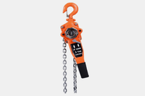
- Ручные рычажные тали: идеально подходят для тяговых и подъемных задач
- Ручные цепные тали: ручной подъем для мест без электричества
- Электрические тали с малой высотой подъема: компактная конструкция для максимальной эффективности использования пространства
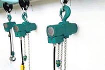
- Пневматические цепные тали: плавное управление для промышленного использования
- Взрывозащищенные ручные цепные тали: искробезопасная конструкция из медного сплава для работы в опасных зонах.
- Взрывозащищенные электрические цепные тали для подъема грузов в опасных зонах
- О
- Случаи
- Новости
- Вопросы и ответы
- Скачать
- Блоги
- Онлайн-инструменты для расчета нагрузки на колесо крана
- VR Панорама
- Связаться с нами
- Почта: sales@hndfcrane.com
- Ватсап: +86 191 3738 6654
- Телеграмма: +86 191 3738 6654
- Тел: +86-373-581 8299
-