
-
Branże
-
Produkcja ogólna
-
Zarządzanie odpadami
-
Prefabrykaty
-
Moc
-
Kamień
-
Papiernictwo
-
Produkcja metalowa
-
Budowa mostu
-
Suwnice portowe: do obsługi kontenerów i materiałów masowych
-
Suwnice dla przemysłu naftowego i gazowego: Zwiększ wydajność operacyjną
-
Dźwigi morskie zapewniające efektywny załadunek ładunków na statkach
-
Suwnice dla przemysłu motoryzacyjnego: wydajne rozwiązania automatyzacyjne
-
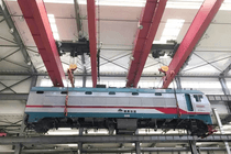
Rozwiązania suwnicowe dla kolei: układanie torów, konserwacja taboru kolejowego i obsługa kontenerów
-
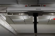
Suwnice pomostowe do żywności i napojów: niezawodne rozwiązania zapewniające efektywną obsługę
-
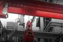
Suwnice pomostowe do wydajnej produkcji cementu, szkła, cegieł i prefabrykatów betonowych
-
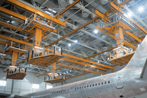
Suwnice dla przemysłu lotniczego: konserwacja i montaż samolotów
-
Suwnice pomostowe dla lotnictwa i kosmonautyki: precyzyjne podnoszenie podczas startów i transportu rakiet
-
-
Produkty
-
Suwnice
-
Suwnice jednodźwigarowe
-
Suwnice dwudźwigarowe
-
Suwnice pomostowe jednodźwigarowe typu europejskiego
-
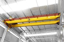
Suwnice dwudźwigarowe typu europejskiego
-
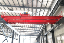
Suwnice przeciwwybuchowe
-
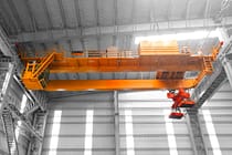
Chwytaki i suwnice magnetyczne
-
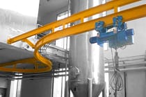
Żurawie jednoszynowe
-
Suwnice odlewnicze
-
Suwnice izolacyjne
-
Suwnice o niskim prześwicie
-
Chwyć dźwigi pomostowe
-

Suwnice kadziowe
-
Suwnice podwieszane
-
Suwnice elektromagnetyczne
-
Dźwigi stanowiskowe
-
Suwnice mostowe wolnostojące
-
Suwnica mostowa montowana na suficie
-
Suwnice ręczne
-
-
Suwnice
-
Suwnice półbramowe
-
Jednodźwigarowe suwnice bramowe
-
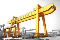
Suwnice bramowe dwudźwigarowe
-
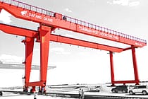
Kontenerowe suwnice bramowe
-
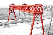
Kratownicowe suwnice bramowe
-
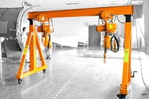
Regulowane suwnice bramowe
-
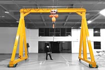
Przenośne suwnice bramowe
-
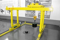
Europejskie suwnice bramowe
-
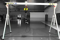
Aluminiowe suwnice bramowe
-
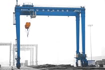
Suwnice bramowe kontenerowe z oponami gumowymi
-
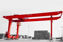
Suwnice bramowe kontenerowe montowane na szynach
-
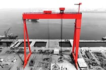
Suwnica bramowa stoczniowa
-
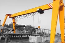
Europejskie suwnice bramowe jednodźwigarowe
-
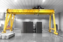
Europejskie suwnice bramowe dwudźwigarowe
-
-
Żurawie
-
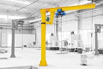
Żurawie wolnostojące
-
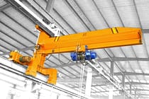
Żurawie przesuwne ścienne
-
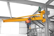
Żurawie ścienne
-
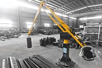
Żurawie wysięgnikowe
-
Elektryczne żurawie wolnostojące
-
Ręczne żurawie wolnostojące
-
Żurawie wysięgnikowe aluminiowe
-
Żurawie przegubowe
-
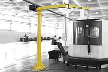
Inteligentne żurawie wysięgnikowe
-
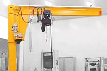
Żurawie wysięgnikowe zgodne ze standardem FEM
-
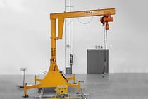
Przenośne żurawie wysięgnikowe
-
-
Specjalne dźwigi
-
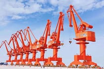
Żurawie portalowe
-
Suwnice do pomieszczeń czystych
-
Mobilne podnośniki łodzi
-
Suwnica bramowa z osłoną do wiercenia tuneli
-
Nośniki bramowe
-
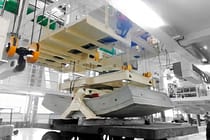
System obsługi segmentów
-
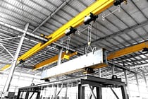
Suwnice transferowe z blokadą cynkową
-
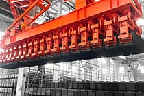
Suwnica do układania bloków węglowych anodowych
-
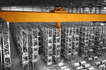
Suwnica układnicowa
-
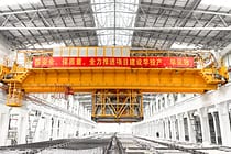
Suwnica z miedzi elektrolitycznej
-
- Wciągniki elektryczne
- Wózki transferowe
-
Suwnice
-
Części dźwigów
-
Chwytaki wiaderkowe
-
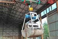
Elektryczny chwytak ze stali nierdzewnej
-
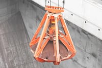
Mechaniczne chwytaki do skórek pomarańczowych na cztery liny
-
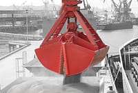
Mechaniczny chwytak czterolinowy typu clamshell
-
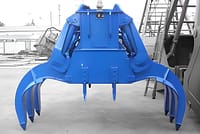
Chwytaki prostokątne elektrohydrauliczne
-
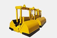
Chwytaki muszlowe elektrohydrauliczne
-
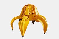
Chwytaki hydrauliczne do skórek pomarańczy, hydrauliczne chwytaki do kaktusów
-
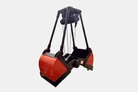
Chwytak silnika elektrycznego
-
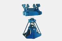
Elektryczny chwytak jednoszynowy z wciągnikiem jednoszynowym
-
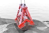
Zdalnie sterowane chwytaki muszlowe
-
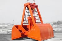
Mechaniczne chwytaki dwulinowe
-
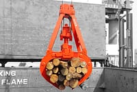
Chwytaki do drewna
-
Pojedynczy chwytak linowy
-
Maszyny do czyszczenia koszy na śmieci
-
Chwytaki pogłębiarskie
-
Chwytaki do przycinania
-
- Rozpieracz dźwigu
-
Części zamienne do dźwigów
-
Snopy dźwigowe
-
krążki linowe
-
Żurawowy bęben linowy
-
Wózek dźwigowy
-
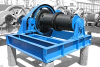
Wyciągarka elektryczna
-
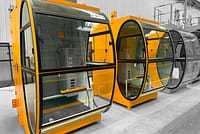
Kabina operatora dźwigu
-
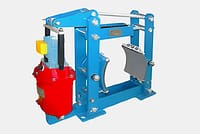
Hamulce suwnicowe
-
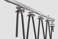
Kable suwnicowe
-
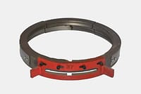
Prowadnice linowe suwnic
-
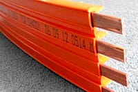
Przewody suwnicowe i linie zasilające
-
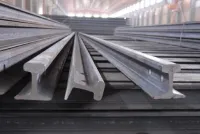
Szyny suwnicowe
-
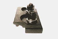
Zaciski szynowe suwnicy
-
Silniki suwnic
-
Reduktory suwnicowe
-
Sprzęgła do suwnicy
-
- Koła dźwigu
-
Chwytaki wiaderkowe
- Firma
- Kontakt


-
Branże
-
Produkcja ogólna
-
Zarządzanie odpadami
-
Prefabrykaty
-
Moc
-
Kamień
-
Papiernictwo
-
Produkcja metalowa
-
Budowa mostu
-
Suwnice portowe: do obsługi kontenerów i materiałów masowych
-
Suwnice dla przemysłu naftowego i gazowego: Zwiększ wydajność operacyjną
-
Dźwigi morskie zapewniające efektywny załadunek ładunków na statkach
-
Suwnice dla przemysłu motoryzacyjnego: wydajne rozwiązania automatyzacyjne
-
Rozwiązania suwnicowe dla kolei: układanie torów, konserwacja taboru kolejowego i obsługa kontenerów
-
Suwnice pomostowe do żywności i napojów: niezawodne rozwiązania zapewniające efektywną obsługę
-
Suwnice pomostowe do wydajnej produkcji cementu, szkła, cegieł i prefabrykatów betonowych
-
Suwnice dla przemysłu lotniczego: konserwacja i montaż samolotów
-
Suwnice pomostowe dla lotnictwa i kosmonautyki: precyzyjne podnoszenie podczas startów i transportu rakiet
-
-
Produkty
-
Suwnice
-
Suwnice jednodźwigarowe
-
Suwnice dwudźwigarowe
-
Suwnice pomostowe jednodźwigarowe typu europejskiego
-
Suwnice dwudźwigarowe typu europejskiego
-
Suwnice przeciwwybuchowe
-
Chwytaki i suwnice magnetyczne
-
Żurawie jednoszynowe
-
Suwnice odlewnicze
-
Suwnice izolacyjne
-
Suwnice o niskim prześwicie
-
Chwyć dźwigi pomostowe
-
Suwnice kadziowe
-
Suwnice podwieszane
-
Suwnice elektromagnetyczne
-
Dźwigi stanowiskowe
-
Suwnice mostowe wolnostojące
-
Suwnica mostowa montowana na suficie
-
Suwnice ręczne
-
-
Suwnice
-
Suwnice półbramowe
-
Jednodźwigarowe suwnice bramowe
-
Suwnice bramowe dwudźwigarowe
-
Kontenerowe suwnice bramowe
-
Kratownicowe suwnice bramowe
-
Regulowane suwnice bramowe
-
Przenośne suwnice bramowe
-
Europejskie suwnice bramowe
-
Aluminiowe suwnice bramowe
-
Suwnice bramowe kontenerowe z oponami gumowymi
-
Suwnice bramowe kontenerowe montowane na szynach
-
Suwnica bramowa stoczniowa
-
Europejskie suwnice bramowe jednodźwigarowe
-
Europejskie suwnice bramowe dwudźwigarowe
-
-
Żurawie
-
Żurawie wolnostojące
-
Żurawie przesuwne ścienne
-
Żurawie ścienne
-
Żurawie wysięgnikowe
-
Elektryczne żurawie wolnostojące
-
Ręczne żurawie wolnostojące
-
Żurawie wysięgnikowe aluminiowe
-
Żurawie przegubowe
-
Inteligentne żurawie wysięgnikowe
-
Żurawie wysięgnikowe zgodne ze standardem FEM
-
Przenośne żurawie wysięgnikowe
-
-
Specjalne dźwigi
-
Żurawie portalowe
-
Suwnice do pomieszczeń czystych
-
Mobilne podnośniki łodzi
-
Suwnica bramowa z osłoną do wiercenia tuneli
-
Nośniki bramowe
-
System obsługi segmentów
-
Suwnice transferowe z blokadą cynkową
-
Suwnica do układania bloków węglowych anodowych
-
Suwnica układnicowa
-
Suwnica z miedzi elektrolitycznej
-
- Wciągniki elektryczne
- Wózki transferowe
-
Suwnice
-
Części dźwigów
-
Chwytaki wiaderkowe
-
Elektryczny chwytak ze stali nierdzewnej
-
Mechaniczne chwytaki do skórek pomarańczowych na cztery liny
-
Mechaniczny chwytak czterolinowy typu clamshell
-
Chwytaki prostokątne elektrohydrauliczne
-
Chwytaki muszlowe elektrohydrauliczne
-
Chwytaki hydrauliczne do skórek pomarańczy, hydrauliczne chwytaki do kaktusów
-
Chwytak silnika elektrycznego
-
Elektryczny chwytak jednoszynowy z wciągnikiem jednoszynowym
-
Zdalnie sterowane chwytaki muszlowe
-
Mechaniczne chwytaki dwulinowe
-
Chwytaki do drewna
-
Pojedynczy chwytak linowy
-
Maszyny do czyszczenia koszy na śmieci
-
Chwytaki pogłębiarskie
-
Chwytaki do przycinania
-
- Rozpieracz dźwigu
-
Części zamienne do dźwigów
-
Snopy dźwigowe
-
krążki linowe
-
Żurawowy bęben linowy
-
Wózek dźwigowy
-
Wyciągarka elektryczna
-
Kabina operatora dźwigu
-
Hamulce suwnicowe
-
Kable suwnicowe
-
Prowadnice linowe suwnic
-
Przewody suwnicowe i linie zasilające
-
Szyny suwnicowe
-
Zaciski szynowe suwnicy
-
Silniki suwnic
-
Reduktory suwnicowe
-
Sprzęgła do suwnicy
-
- Koła dźwigu
-
Chwytaki wiaderkowe
- Firma
- Kontakt



Ladle Overhead Crane Structural Components and Functions
Spis treści
Ladle overhead cranes are critical equipment in steelmaking plants, designed to safely handle and transport molten metal under demanding operating conditions. Their structural design and safety systems directly affect lifting reliability and operational safety. This article explains the main components of a ladle overhead crane and the function of each part.
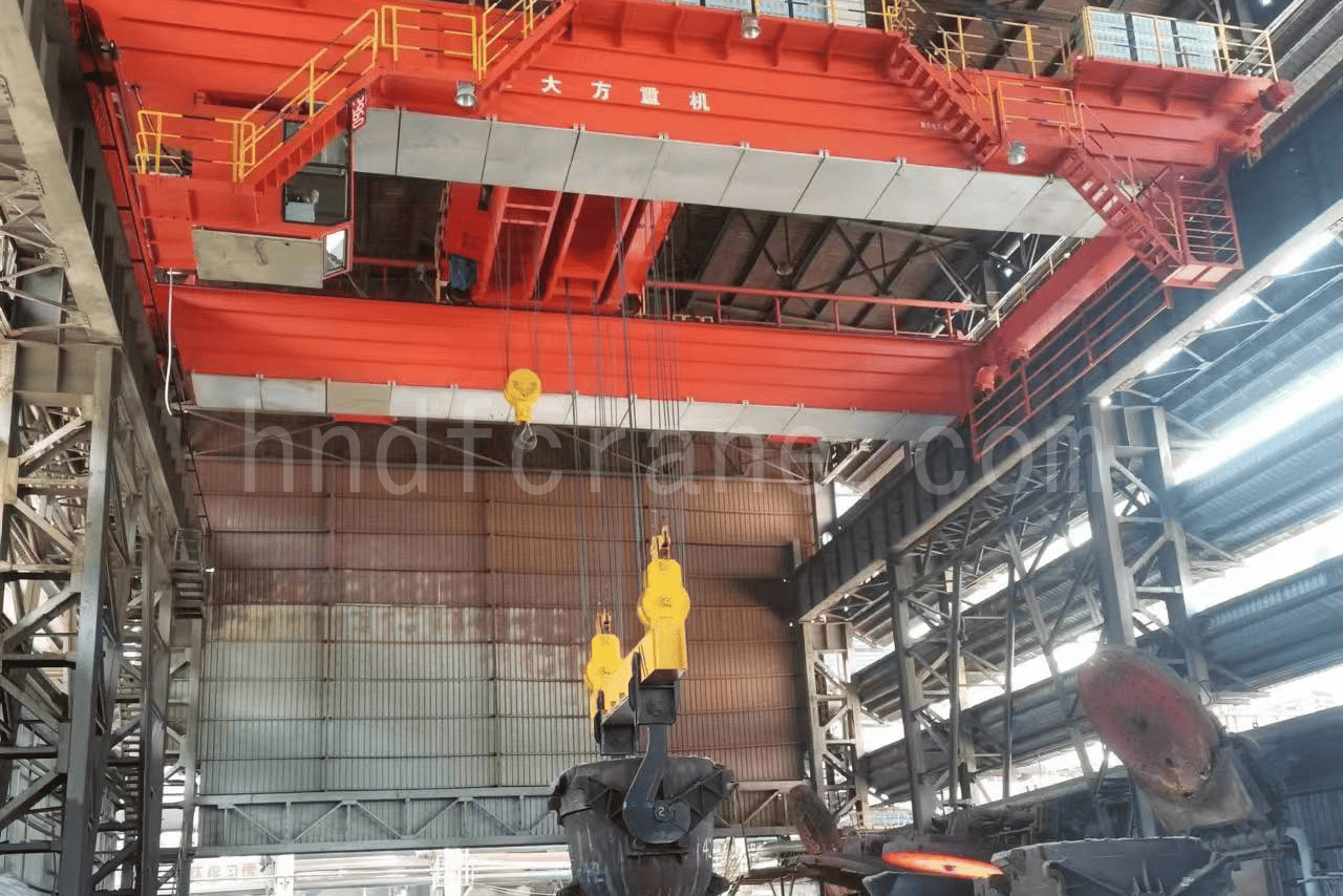
Composition of the Ladle Overhead Crane
A suwnica kadziowa is mainly composed of four major parts: the bridge, the trolley (including the spreader), the crane travel mechanism, and the electrical equipment. Different construction types are adopted according to different operating requirements.
The bridge is generally a double-girder or four-girder structure composed of box-type main girders and end carriages. Rails are set on the top flange plates of the main girders for the trolley to travel on. When narrow-girder main girders are used, the electrical control equipment is placed on the walkway beside the main girders; when wide-girder main girders are used, the electrical control equipment is generally arranged inside the main girders.
The trolley is the core component of the crane. The bridge carries one trolley or a main and an auxiliary trolley, and the trolleys travel independently. The trolley is equipped with a hoisting mechanism and a travel mechanism, with the spreader below the hoisting mechanism. The trolley travel mechanism uses either centralized drive or individual drive.
The crane travel mechanisms all use individual drive, some with two-corner drive and some with four-corner drive.
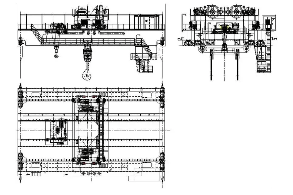
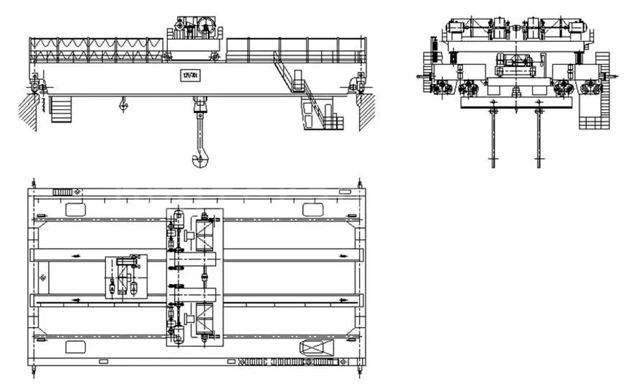
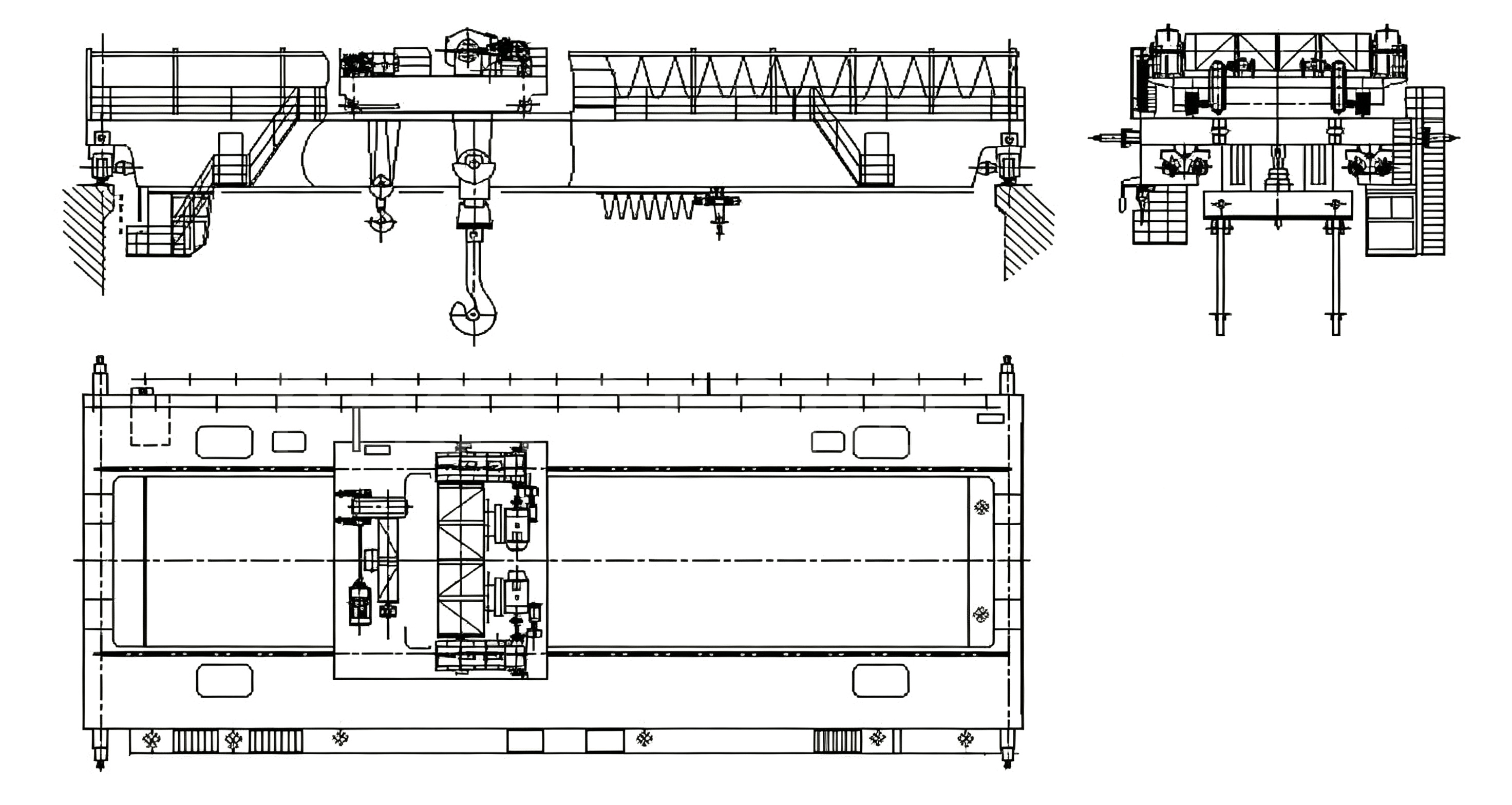
Figures 2-1 to 2-3 below are examples of some ladle overhead crane models, from which the construction characteristics of ladle overhead cranes can be understood.
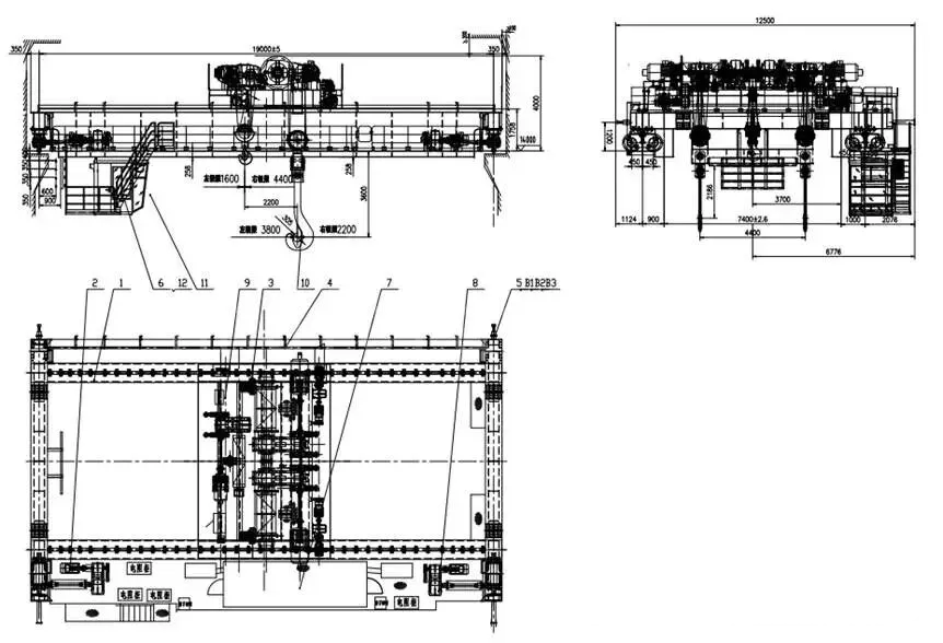
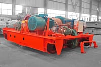
Wózek dźwigowy
The trolley is mainly composed of three major components: the hoisting mechanism, the trolley travel mechanism, and the trolley frame. According to different operating requirements of the crane, the trolley has different arrangements; see the examples in Figures 2-1 to 2-3.
Mechanizm podnoszący
The hoisting mechanism generally consists of a drive device, a wire rope reeving system, a load-handling device, and safety protection devices. Some also use an electric hoist as an auxiliary hoisting mechanism.
The drive device includes the motor, coupling, compensation shaft, brake, reducer, and other components. When the drive device uses conventional control or stator voltage regulation speed control, the motor is a wound-rotor type; when variable-frequency speed control is used, it is a variable-frequency motor. For a main hoisting mechanism with two sets of drive devices, when one motor or one set of electrical control devices fails, the other set of drive devices shall be able to complete one working cycle while lifting the rated lifting capacity.
The wire rope reeving system includes the wire rope, drum assembly, fixed sheave assembly and wire rope equalizer, and movable sheave assembly. When the main hoisting mechanism has two lifting points, a four-rope reeving system is used; when it has a single lifting point, a two-rope reeving system is used.
The load-handling device includes the hook, non-detachable spreader (including various fixed lifting beams and fixed gantry hooks), and detachable spreader (including various detachable lifting beams and detachable gantry hooks).
For safety, the hoisting mechanism is equipped with an overload limiter, a lifting height limiter, and an overspeed switch. The upper limit position of the height limiter is a dual protection device of different forms; the first stage is generally the lifting height limiter at the drum end, and the second stage is a weight (hammer) limit switch. A safety brake may also be provided as needed.
In the hoisting mechanism, the motor is connected to the reducer through a coupling; the low-speed shaft of the reducer drives the drum, which then drives the load-handling device through the wire rope reeving system. As long as the motor’s forward and reverse rotation is controlled, the load-handling device can be raised and lowered.
According to different operating requirements, the composition of the hoisting mechanism varies. Figures 2-4 to 2-6 are some examples.
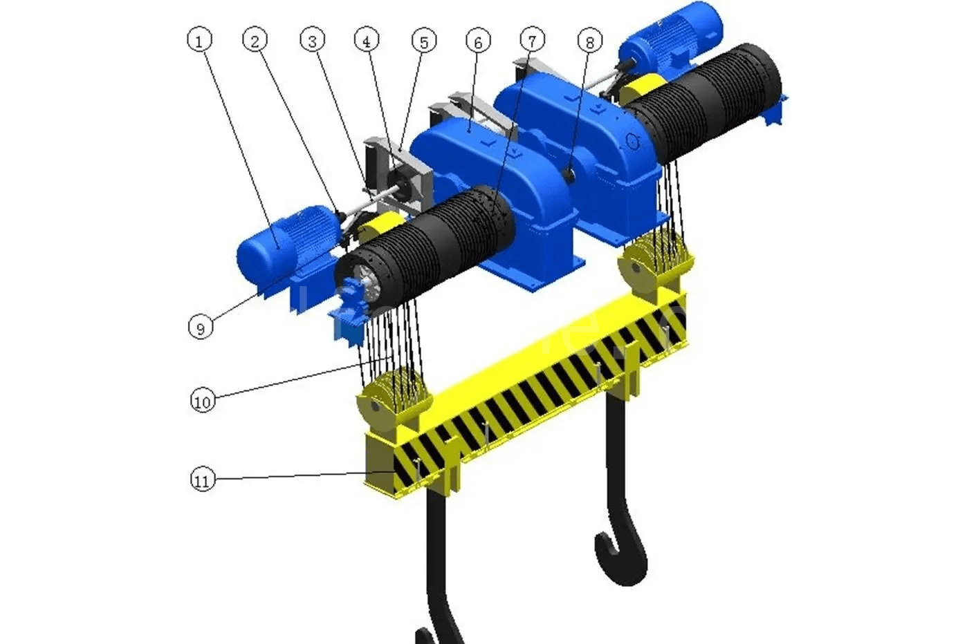
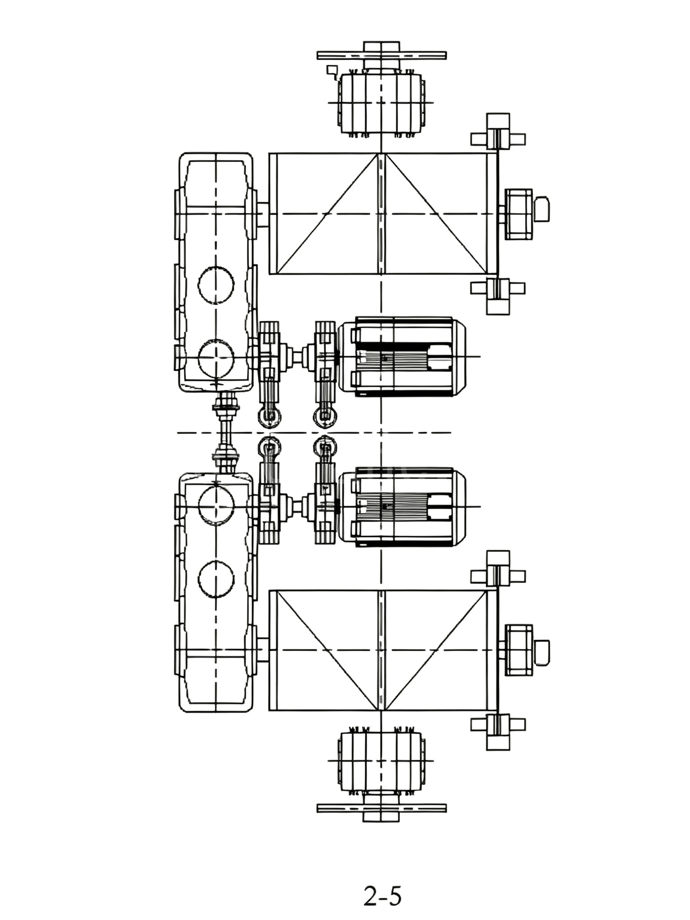
The hoisting mechanism shown in Figure 2-5 has two lifting points, utilizing a four-rope reeving system and two sets of drive units. The two reducers are connected at the high-speed end by a coupling, and a safety brake is installed on the drum.
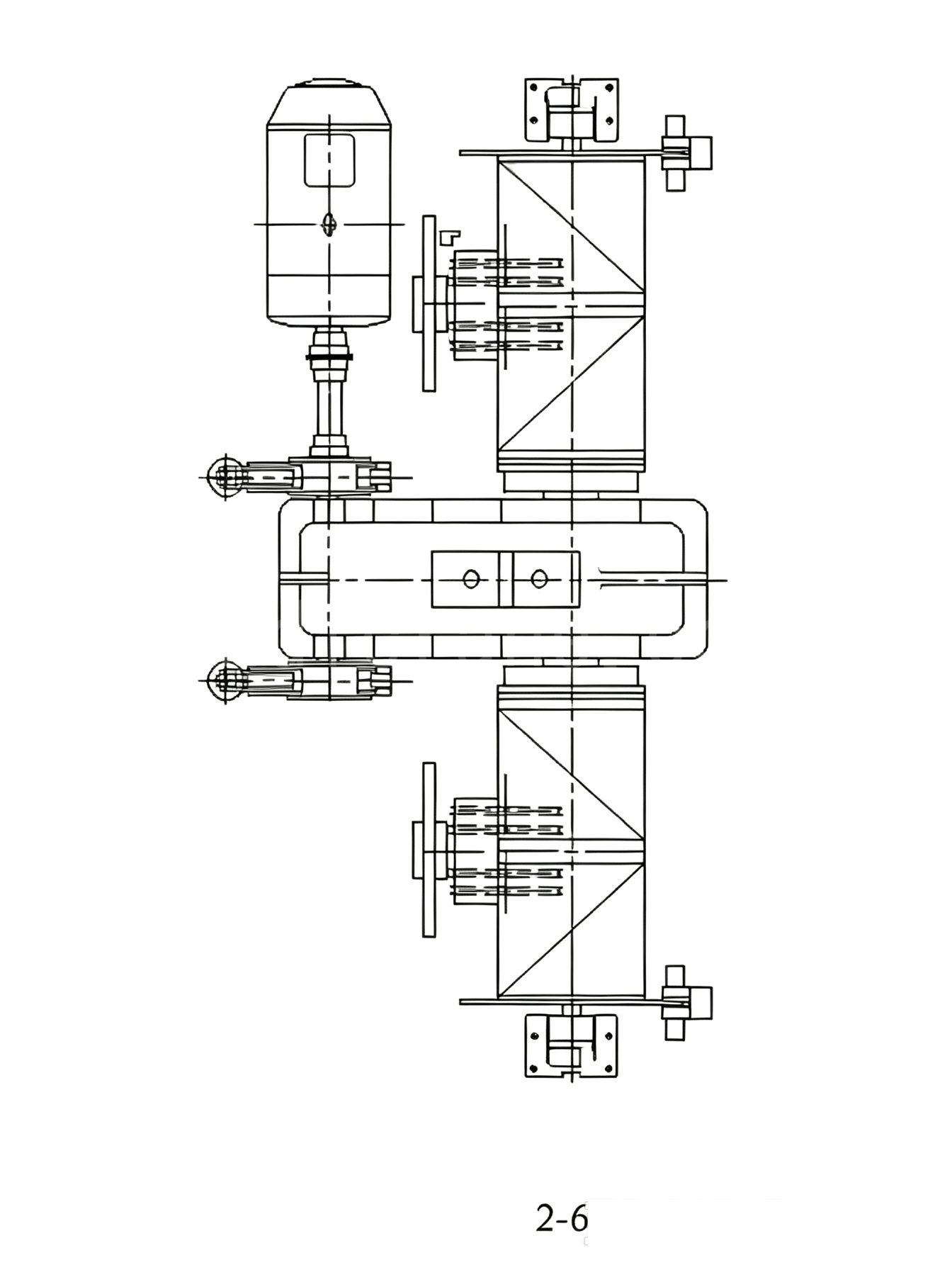
Figure 2-6 also has two lifting points, but the arrangement of the four-rope reeving system is different from that in Figure 2-5. It features one set of drive unit, and a safety brake is installed on the drum.
Trolley Travel Mechanism
The trolley travel mechanism is mainly composed of a travel drive device and travel support. The travel drive device is mainly composed of the motor, reducer, brake, and other components. The travel support mainly includes the wheels and wheel equalizing beams.
The trolley travel mechanism uses centralized drive or individual drive. Some large-tonnage crane trolleys use wheel equalizing beams to reduce wheel load.
The drive device of the trolley travel mechanism generally uses the motor to drive a vertical reducer, whose low-speed shaft drives the driving wheels. When the drive device uses conventional control or stator voltage regulation speed control, the motor is a wound-rotor type; when variable-frequency speed control is used, it is a variable-frequency motor.
For safe trolley travel, a trolley travel limit switch and buffers are provided. When the trolley travels near the limit position, the limit switch operates and the power to the travel mechanism is cut off; the buffer then absorbs the remaining energy, and the travel mechanism can only travel in the reverse direction.
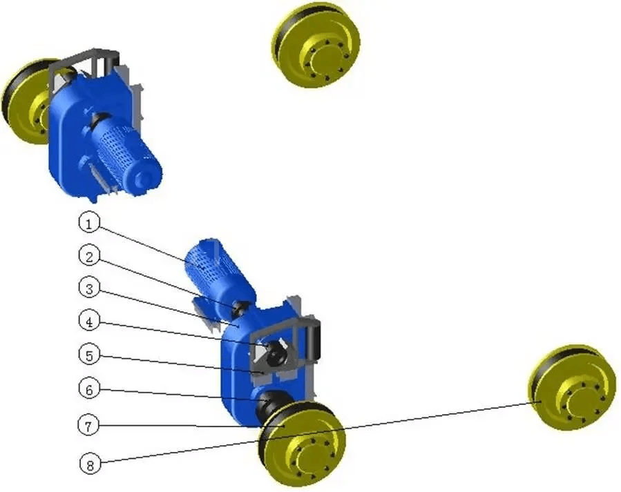
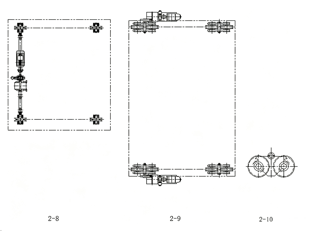
According to different situations, the trolley travel has corresponding constructions. Figure 2-7 is a commonly used trolley travel mechanism layout in four-girder, four-track ladle overhead cranes, using individual drive. There are also other layouts depending on the situation. Figure 2-8 uses centralized drive, and Figure 2-9 is another design with individual drive. For trolleys with large lifting capacity, wheels can be added using a wheel equalizing beam structure; Figure 2-10 is one form of wheel equalizing beam structure.
Mechanizm jazdy dźwigu
The crane travel mechanism is mainly composed of a travel drive device and travel support. The travel drive device is mainly composed of the motor, reducer, brake, and other components. The travel support mainly includes the wheels and wheel equalizing beams. The crane travel mechanism mostly uses individual drive, generally with two or four sets of drive devices. When the main girders are narrow-girder structures, the travel mechanism is generally installed on the bridge walkway, while for wide-girder structures the travel mechanism is generally installed at the ends inside the main girders.
When conventional control or stator voltage regulation speed control is used, the motor is a wound-rotor type; when variable-frequency speed control is used, it is a variable-frequency motor.
The crane is equipped with limit switches and buffers to prevent the crane from traveling to the plant limit position or colliding with adjacent cranes, so as to reduce damage to the crane and reduce the discomfort caused to the driver by collision. When the crane travels near the plant limit position or near an adjacent crane, the limit switch operates and the power to the travel mechanism is cut off; the buffer then absorbs the remaining energy. At this point, the travel mechanism can only travel in the reverse direction. The buffers generally use spring or hydraulic buffers.
For a crane travel mechanism with four sets of drive devices, some users require that when the drive devices on one side fail, the drive devices on the other side shall be able to complete one working cycle while lifting the rated lifting capacity through electrical switching.
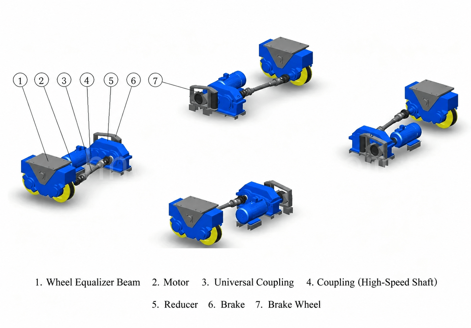
For large-tonnage cranes, the travel support uses wheel equalizing beams to reduce wheel load. In addition, horizontal wheels may be added per contract requirements.
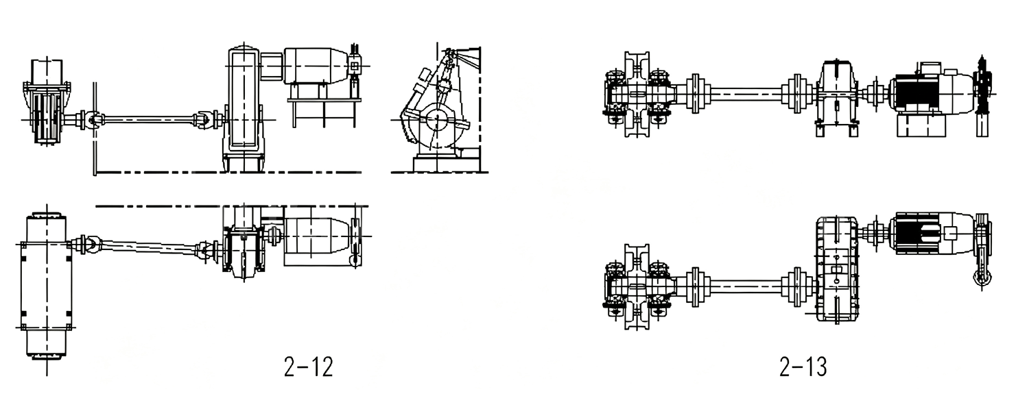
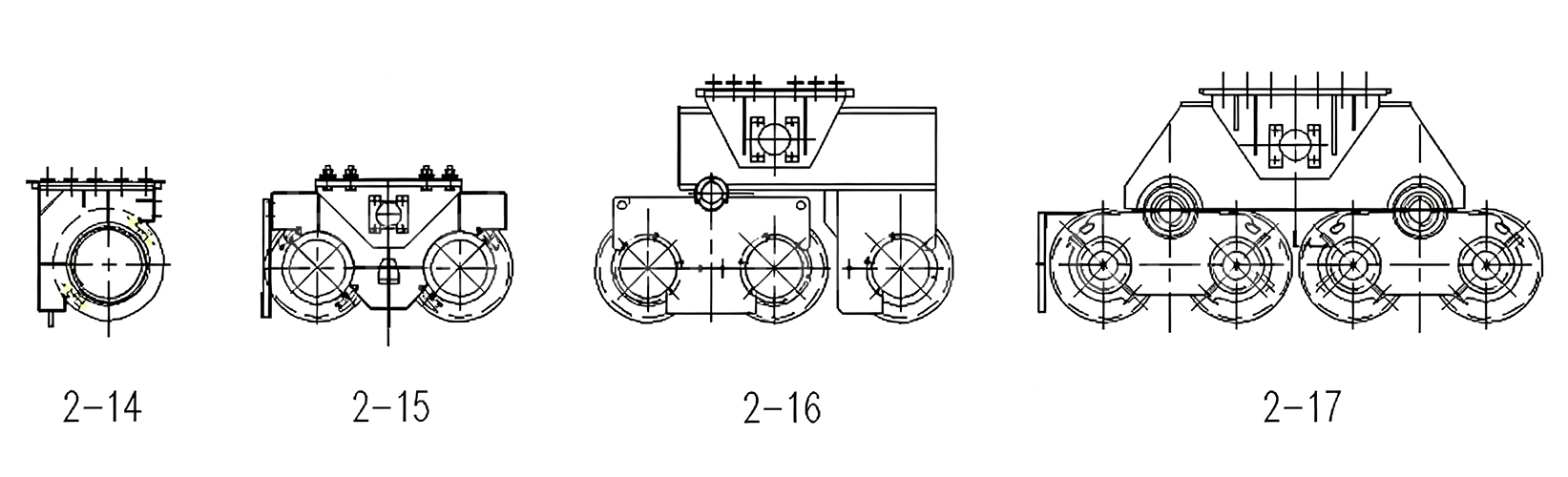
Figure 2-11 is a commonly used crane travel mechanism layout, an example using a horizontal parallel-shaft reducer drive with the travel support being wheel equalizing beams. Figure 2-12 is an example using a vertical parallel-shaft reducer with the travel support being wheel equalizing beams. Small-tonnage cranes use the Figure 2-13 type, with the travel support being a single wheel group.
In the travel support, small-tonnage cranes have two wheel groups on each end carriage, or the Figure 2-14 wheel seat is installed under the end carriage. For large-tonnage cranes, different wheel equalizing beams or combinations from Figures 2-15 to 2-17 are selected to support different loads.
Bridge Frame
The bridge is the main structure and the mounting base for the trolley, crane travel mechanism, and electrical equipment. The bridge is mainly composed of the main girders, end carriages, walkway, trolley cable carrier, trolley rails, maintenance platform and ladder, platform, railings, and other components.
The bridge is an important load-bearing member of the crane, with sufficient strength, stiffness, and overall stability, meeting national standards and contract requirements, and ensuring the normal operation of the crane. The bridge of a ladle overhead crane is divided into double-girder (see Figures 2-2 and 2-3) and four-girder (see Figure 2-1) types. A heat shield is provided below the bottom flange plate of the main girders. After the complete-machine test, when the empty trolley is at the limit position, the camber of the main girders shall not be less than 0.7S/1000 (where S is the crane span), and the maximum camber value is controlled within the S/10 range at mid-span.
According to different requirements or situations, the main girders can be designed as center-rail box-type narrow girders, semi-off-rail box-type narrow girders, off-rail box-type narrow girders, or off-rail box-type wide girders. The top cover plate of the main girders is provided with rails for the trolley to travel on. The rails can be fixed by welded clamp plates or by adjustable combined rail clamps (per contract requirements). When the main girders are narrow-girder structures, the electrical equipment is installed on the walkway; when the ambient temperature cannot meet the normal working requirements of the electrical equipment, a cooled electrical room is provided, and the electrical room is fitted with a heat-insulating layer. When the main girders are wide-girder structures, the electrical equipment is generally installed in an electrical room inside the main girders; when the ambient temperature cannot meet the normal working requirements of the electrical equipment, the electrical room is fitted with air conditioning and a heat-insulating layer.
Buffers are provided on both sides of the bridge, working with the crane travel limit switches, so that the crane has the function of first cutting power and decelerating before stopping. The railings are provided with railing doors with electrical interlock protection devices. When any interlocked railing door is opened, the relevant mechanisms of the crane are automatically de-energized; the relevant mechanisms can work normally only when the railing door is closed. On the crane power conductor rail side, a conductor rail guard and a cage (or platform) are provided. The conductor rail guard prevents the hook or wire rope from touching the power conductor rail, and the cage (or platform) is used to install and maintain the current collectors. The trolley maintenance platform facilitates trolley maintenance.
Kabina operatora
The operator cabin is the workplace where the operator controls the crane. Suspended below the main girders, it is an enclosed, air-conditioned, insulated, full-view, heat-insulating structure with a transparent view window at the bottom. The doors and windows use aluminum-alloy frames with tempered safety glass. The cab is equipped with a comfortable adjustable soft seat (adjustable up/down and front/back). The cab contains electrical control equipment with concealed wiring, and the control devices are easy to operate. The indoor and outdoor connections are made through terminal boxes for ease of maintenance. The floor is covered with insulating rubber matting, which is flame-retardant, non-conductive, and non-slip. The cab is equipped with an alarm, electric bell, fire extinguisher, electric fan, dedicated heating/cooling air conditioner, and other safety devices, as well as various instruments and a lighting system. The driver can observe the operating state of each mechanism at any time to ensure safe crane operation. Insulating rubber matting is laid in the driver’s cab.
Electrical Room
The electrical room is set inside the main girders (the electrical house is used for narrow-girder structures and is placed on the main girder walkway). The inner walls around the main girder electrical room are provided with an insulating sandwich layer filled with insulating material; sealed doors are installed at both ends; the upper part of the doors is provided with observation glass windows; the doors are provided with locks and handles, and the doors open outward.
The electrical room has the functions of heat insulation, dust prevention, and air-conditioning cooling, preventing heat transfer and dust from entering the room. To allow maintenance personnel to maintain the electrical equipment normally, a passage of more than 600 mm is left in the electrical room, and the clear height is not less than 2.2 m. Insulating rubber matting is laid on the aisle surface. An insulating protective railing is provided in front of the electrical panel rack, with a reasonable maintenance space between the railing and the electrical panel rack. An industrial special cooling fan is installed in the main girder electrical room, so that the electrical components are not affected by the outside temperature and can always work safely and reliably.
Through the simple analysis and explanation of the ladle overhead crane above, this article explains the forms and functions of the various structures of a ladle overhead crane, so that readers can gain a certain understanding and design in a standardized manner in the future, avoiding some unnecessary mistakes and trouble.

Jestem Cindy, mam 10 lat doświadczenia w branży dźwigowej i zgromadziłam bogactwo wiedzy zawodowej. Wybrałam satysfakcjonujące dźwigi dla ponad 500 klientów. Jeśli masz jakiekolwiek potrzeby lub pytania dotyczące dźwigów, skontaktuj się ze mną, wykorzystam swoją wiedzę specjalistyczną i praktyczne doświadczenie, aby pomóc Ci rozwiązać problem!
Wyślij zapytanie
- E-mail: sprzedaż@hndfcrane.com
- WhatsApp: +86 191 3738 6654
- Telegram: +86 191 3738 6654
- Tel: +86-373-581 8299
- Faks: +86-373-215 7000
- Dodaj: dzielnica przemysłowa Changnao, miasto Xinxiang, prowincja Henan, Chiny
 WeChat
- Suwnice
- Suwnice dwudźwigarowe
- Suwnice jednodźwigarowe
- Suwnice pomostowe jednodźwigarowe typu europejskiego
- Suwnice przeciwwybuchowe
- Chwytaki i suwnice magnetyczne
- Żurawie jednoszynowe
- Suwnice odlewnicze
- Dźwigi stanowiskowe
- Żurawie
- Żurawie ścienne
- Żurawie przesuwne ścienne
- Żurawie wolnostojące
- Żurawie wysięgnikowe aluminiowe: lekkie, płynnie obracające się ramię ułatwiające podnoszenie
- Żurawie wysięgnikowe Balance: wydajne podnoszenie lekkie przy montażu mechanicznym na krótkich dystansach
- Żurawie wysięgnikowe ręczne wolnostojące: wydajne rozwiązania ręcznego podnoszenia do operacji w ograniczonej przestrzeni
- Elektryczne żurawie wolnostojące: w pełni elektryczne rozwiązanie do szybkiego podnoszenia o dużej ładowności
- Żurawie z wysięgnikiem przegubowym: precyzyjne podnoszenie z elastycznością dwóch ramion
- Suwnice
- Suwnice bramowe dwudźwigarowe
- Suwnice półbramowe
- Jednodźwigarowe suwnice bramowe
- Kratownicowe suwnice bramowe
- Kontenerowe suwnice bramowe
- Regulowane suwnice bramowe
- Przenośne suwnice bramowe
- Europejskie suwnice bramowe
- Branże
- Produkcja ogólna
- Zarządzanie odpadami
- Prefabrykaty
- Moc
- Kamień
- Papiernictwo
- Produkcja metalowa
- Budowa mostu
- Suwnice portowe: do obsługi kontenerów i materiałów masowych
- Suwnice dla przemysłu naftowego i gazowego: Zwiększ wydajność operacyjną
- Dźwigi morskie zapewniające efektywny załadunek ładunków na statkach
- Suwnice dla przemysłu motoryzacyjnego: wydajne rozwiązania automatyzacyjne
- Wciągniki elektryczne
- Elektryczne wciągniki linowe
- Elektryczne wciągniki łańcuchowe
- Wciągniki elektryczne typu europejskiego
- Europejskie wciągniki łańcuchowe elektryczne: płynna praca, niski poziom hałasu i energooszczędność
- Wciągniki dźwigniowe ręczne: idealne do zadań związanych z ciągnięciem i podnoszeniem
- Wciągniki łańcuchowe ręczne: ręczne podnoszenie w miejscach bez zasilania
- Wciągniki elektryczne o niskim prześwicie: kompaktowa konstrukcja zapewniająca maksymalną efektywność wykorzystania przestrzeni
- Pneumatyczne wciągniki łańcuchowe: płynna obsługa w zastosowaniach przemysłowych
- Wciągniki łańcuchowe ręczne przeciwwybuchowe: konstrukcja ze stopu miedzi odpornego na iskry do stref zagrożonych wybuchem
- Elektryczne wciągniki łańcuchowe przeciwwybuchowe do podnoszenia w strefach niebezpiecznych
- O
- Sprawy
- Aktualności
- Często zadawane pytania
- Pobierać
- Blogi
- Narzędzia do obliczania obciążenia kół dźwigu online
- Panorama VR
- Skontaktuj się z nami
- E-mail: sprzedaż@hndfcrane.com
- WhatsApp: +86 191 3738 6654
- Telegram: +86 191 3738 6654
- Tel: +86-373-581 8299
-