
-
Industries
-

General Manufacturing
-
Waste Handling
-

Precast
-

Power
-

Stone
-

Papermaking
-
Metal Production
-
Bridge Construction
-

Port Cranes: For Container and Bulk Material Handling
-

Overhead Cranes for Petroleum and Gas Industry: Enhance Operational Efficiency
-

Marine Cranes for Efficient Cargo Loading on Ships
-

Overhead Cranes for the Automotive Industry: Efficient Automation Solutions
-

Overhead Crane Solutions for Railways: Track Laying, Rolling Stock Maintenance, and Container Handling
-

Overhead Cranes for Food and Beverages: Reliable Solutions for Efficient Handling
-

Overhead Cranes for Efficient Cement, Glass, Brick and Precast Concrete Manufacturing
-

Overhead Cranes for Aviation Industry: Aircraft Maintenance and Assembly
-

Aerospace Overhead Cranes: Precision Lifting for Rocket Launch and Transport
-
-
Products
-
Overhead Cranes
-
Single Girder Overhead Cranes
-

Double Girder Overhead Cranes
-

European Type Single Girder Overhead Cranes
-

European Type Double Girder Overhead Cranes
-

Explosion Proof Overhead Cranes
-

Grab And Magnetic Overhead Cranes
-

Monorail Cranes
-

Foundry Overhead Cranes
-

Insulation Overhead Cranes
-

Low Headroom Overhead Cranes
-

Grab Overhead Cranes
-

Ladle Overhead Cranes
-

Underhung Overhead Cranes
-

Electromagnetic Overhead Cranes
-

Workstation Cranes
-

Free Standing Workstation Bridge Cranes
-

Ceiling Mounted Bridge Crane
-

Manual Overhead Cranes
-
-
Gantry Cranes
-

Semi Gantry Cranes
-

Single Girder Gantry Cranes
-

Double Girder Gantry Cranes
-

Container Gantry Cranes
-
Truss Gantry Cranes
-

Adjustable Gantry Cranes
-

Portable Gantry Cranes
-
European Gantry Cranes
-

Aluminum Gantry Cranes
-

Rubber Tyred Container Gantry Cranes
-

Rail Mounted Container Gantry Cranes
-

Shipyard Gantry Crane
-

European Single Girder Gantry Cranes
-

European Double Girder Gantry Cranes
-
- Jib Cranes
- Special Cranes
- Electric Hoists
- Transfer Carts
-
Overhead Cranes
-
Crane Parts
-
Grab Buckets
-

Electric Stainless Steel Grab Bucket
-

Mechanical Four Rope Orange Peel Grabs
-

Mechanical Four Rope Clamshell Grabs Bucket
-

Electro Hydraulic Rectangular Grabs
-

Electro hydraulic Clamshell Grabs
-

Electro Hydraulic Orange Peel Grabs,Hydraulic Cactus Grab
-

Electric Motor Grab
-

Electric Monorail Grab Bucket with Monorail Hoist
-

Remote Control Clamshell Grabs
-

Mechanical Two Rope Clamshell Grabs
-

Timber Grabs
-

Single Rope Grab Bucket
-

Trash Rack Cleaning Machines
-

Dredging Grabs
-

Trimming Grabs
-
- Crane Spreader
-
Crane Spare Parts
-

Wire Rope Sheaves
-

Crane Rope Drum
-

Crane Trolley
-

Electric Winch
-

Crane Operator Cabin
-

Overhead Crane Brakes
-

Overhead Crane Cables
-

Overhead Crane Rope Guides
-

Overhead Crane Conductors and Power Supply Lines
-

Overhead Crane Rails
-

Overhead Crane Rail Clips
-

Overhead Crane Motors
-

Overhead Crane Reducers
-

Couplings for Overhead Crane
-
- Crane Wheels
-
Grab Buckets
- Company
- Contact


-
Industries
-
General Manufacturing
-
Waste Handling
-
Precast
-
Power
-
Stone
-
Papermaking
-
Metal Production
-
Bridge Construction
-
Port Cranes: For Container and Bulk Material Handling
-
Overhead Cranes for Petroleum and Gas Industry: Enhance Operational Efficiency
-
Marine Cranes for Efficient Cargo Loading on Ships
-
Overhead Cranes for the Automotive Industry: Efficient Automation Solutions
-
Overhead Crane Solutions for Railways: Track Laying, Rolling Stock Maintenance, and Container Handling
-
Overhead Cranes for Food and Beverages: Reliable Solutions for Efficient Handling
-
Overhead Cranes for Efficient Cement, Glass, Brick and Precast Concrete Manufacturing
-
Overhead Cranes for Aviation Industry: Aircraft Maintenance and Assembly
-
Aerospace Overhead Cranes: Precision Lifting for Rocket Launch and Transport
-
-
Products
-
Overhead Cranes
-
Single Girder Overhead Cranes
-
Double Girder Overhead Cranes
-
European Type Single Girder Overhead Cranes
-
European Type Double Girder Overhead Cranes
-
Explosion Proof Overhead Cranes
-
Grab And Magnetic Overhead Cranes
-
Monorail Cranes
-
Foundry Overhead Cranes
-
Insulation Overhead Cranes
-
Low Headroom Overhead Cranes
-
Grab Overhead Cranes
-
Ladle Overhead Cranes
-
Underhung Overhead Cranes
-
Electromagnetic Overhead Cranes
-
Workstation Cranes
-
Free Standing Workstation Bridge Cranes
-
Ceiling Mounted Bridge Crane
-
Manual Overhead Cranes
-
-
Gantry Cranes
-
Semi Gantry Cranes
-
Single Girder Gantry Cranes
-
Double Girder Gantry Cranes
-
Container Gantry Cranes
-
Truss Gantry Cranes
-
Adjustable Gantry Cranes
-
Portable Gantry Cranes
-
European Gantry Cranes
-
Aluminum Gantry Cranes
-
Rubber Tyred Container Gantry Cranes
-
Rail Mounted Container Gantry Cranes
-
Shipyard Gantry Crane
-
European Single Girder Gantry Cranes
-
European Double Girder Gantry Cranes
-
- Jib Cranes
- Special Cranes
- Electric Hoists
- Transfer Carts
-
Overhead Cranes
-
Crane Parts
-
Grab Buckets
-
Electric Stainless Steel Grab Bucket
-
Mechanical Four Rope Orange Peel Grabs
-
Mechanical Four Rope Clamshell Grabs Bucket
-
Electro Hydraulic Rectangular Grabs
-
Electro hydraulic Clamshell Grabs
-
Electro Hydraulic Orange Peel Grabs,Hydraulic Cactus Grab
-
Electric Motor Grab
-
Electric Monorail Grab Bucket with Monorail Hoist
-
Remote Control Clamshell Grabs
-
Mechanical Two Rope Clamshell Grabs
-
Timber Grabs
-
Single Rope Grab Bucket
-
Trash Rack Cleaning Machines
-
Dredging Grabs
-
Trimming Grabs
-
- Crane Spreader
-
Crane Spare Parts
-
Wire Rope Sheaves
-
Crane Rope Drum
-
Crane Trolley
-
Electric Winch
-
Crane Operator Cabin
-
Overhead Crane Brakes
-
Overhead Crane Cables
-
Overhead Crane Rope Guides
-
Overhead Crane Conductors and Power Supply Lines
-
Overhead Crane Rails
-
Overhead Crane Rail Clips
-
Overhead Crane Motors
-
Overhead Crane Reducers
-
Couplings for Overhead Crane
-
- Crane Wheels
-
Grab Buckets
- Company
- Contact


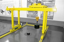
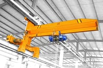
Free Standing Jib Crane Installation
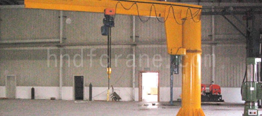
Free standing jib crane, beautiful appearance, flexible and reliable, can be widely used in various occasions such as workshop processing, assembly line, warehouse, maintenance section, test room, etc., lifting materials and transporting shifting within a certain range, they will make your post work more convenient, faster and more efficient.
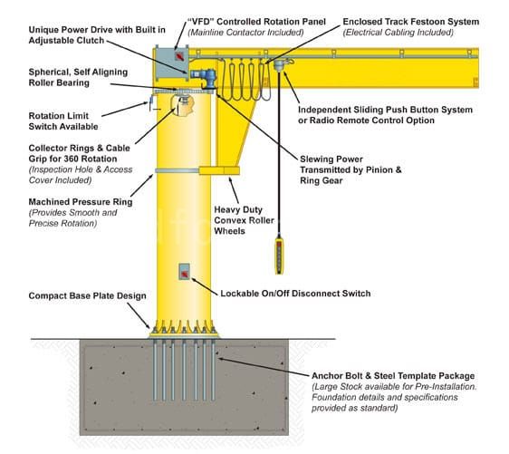
Structure sketch and composition
Column-mounted jib crane with 360° slewing angle, the main components are:
- Rotating arm, including running trolley assembly, cable slider, buffer, end cover, etc.
- Column, including upper and lower support plate, bearing and vertical shaft.
- Electrical parts, including main switch, cable sheath, flat cable, etc.
- Rated lifting weight label, manufacturer’s label.
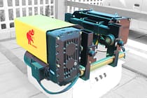
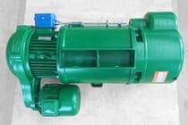
- Electric chain hoist.
- Ground bolts or Anka anchor bolts (depending on the user’s installation conditions).
Free standing jib crane installation
1.Safety rules for assembly and installation:
All high-strength bolt connections must be tightened correctly, and other common bolts cannot replace high-strength bolts. Bolt fasteners must be replaced after five times of disassembles and rotations. High-strength bolts only the appropriate tightening torque to ensure that the bolts tighten without loosening. Unless the specified tightening torque is too high, it is not allowed to lubricate the bolt-forbidden firmware. Retighten all bolt fasteners 1 to 2 months after they are put into service. Defective bolt fasteners must be replaced. Check the provision of pin connection. The groove of the elastic pin must be outward, otherwise it will lead to wear. Hoists, spreaders, and loads must be suspended from the trolley using flexible connections; steel connections can generate uncontrollable forces and lead to fatigue breakage. For towing cables, all flat cables with cold-resistant plastic are used. The cables ‘ insulated wires and grounding protection conductorsshould all be painted yellow-green. The grounding protection conductor is not allowed to be connected to bolts or screws for fastening, the grounding connection point must be prevented from loosening (e.g. by using serrated anti-loosening gaskets), and the grounding protection conductor is not allowed to conduct working current. Provide a power supply switch for connecting the power supply and jib crane power line, it should be able to cut off all phase lines of the jib crane power supply, the switch should be placed close to the jib crane and easily accessible place, and the place should be conspicuous signs. When carrying out maintenance and safety work, the power supply connection switch must be padlocked to prevent accidental or unauthorized power supply.
2.Installation of column jib crane columns:
Check the size of concrete foundation ground bolts and column chassis holes according to the foundation size drawing. Pull the power supply cable (provided by the customer) out of the foundation laying cable pipe in sufficient length (generally about 2~5m). Pass the power supply cable through the opening of the chassis plate, lead it to the switch opening, and tie it firmly. Install the column upwards on the foundation. Adjust the column to be vertical. Generally use a latitude and longitude meter or a measuring hammer on the vertical axis to verify the vertical adjustment of the column (the column body of the column cannot be used as the adjustment reference). Secure the column to the foundation with bolts, making sure they are properly and evenly tightened, and tighten them after the column is adjusted.
3.Installation of wall jib crane brackets:
According to the structure of the building object (generally reinforced concrete or turned wall and reinforced concrete H-beam column) at the user’s site (design and make brackets of sufficient strength and rigidity and reliable connection. Place the brackets in place and tighten the nuts. Make sure the brackets are in a vertical position so that the swivel arm can rest in any position. Generally, check the bracket verticality and adjust it using a warp beam or a magnetic wire drop magnetic gradual drop on the vertical axis of the swing arm. Reliably tighten the bracket to the column or wall, making sure all bolts are tightened evenly and correctly. After adjustment, lock the nut tight.
4 .Installation of the rotary arm:
Installation method of jib crane with slewing angle ≥ 300°.
Method 1: Support through-shaft plus thrust bearing type installation steps are as follows.
Take off the pre-installed support shaft + thrust bearing from the upper end of the column. Place the cantilever between the upper and lower support plates, and put the thrust bearing on top of the support plate to ensure the coaxiality of the sleeve hole and bearing hole in the longitudinal axis of the rotating arm. Apply a small amount of lubricating oil on the support through-shaft and insert the coaxial with keeper plate into the through-hole from top to bottom until the keeper plate fits closely with the upper support plate. Turn the through-axis, adjust the position of the holding plate, and fix the holding plate of the through-axis on the upper support with bolts. After the trial rotation of the rotary arm is flexible, put the cable slider (or cable slider), running trolley, buffer, etc. on the arm and tighten all the bolts and nuts. In order to compensate for the adjustment, the bolted connections should be checked and retightened 1~2 months after delivery for use.
Method 2: Support bearing plus composite bearing type installation procedure.
Before installing the cantilever, remove the protective grease and paint in the tapered hole, clean and dry the through hole. Inject grease in the lubrication recess of the composite bearing, giving priority to lithium grease that is not easy to age, with particle additives shall not be used. Place the cantilever arm between the upper and lower support plates, and install the thrust bearing between the lower support plate and the rotating arm. Insert the supporting taper shaft into the tapered hole of the slewing arm through the composite bearing hole, and should ensure the bonding of the tapered shaft with the tapered shaft hole. Couple the slewing taper shaft with M12*140 bolts, spacers and lock nuts to the swing arm and tighten them (the top and bottom are the same). After the cantilever is rotated flexibly, put the cable slider (or cable slider), running trolley and buffer on the arm and tighten the bolt connections.
Installation method of jib arm of jib crane with rotation angle ≤ 300°.
Bolt the drive unit (gear motor) to the swivel arm on the jib and tighten it. Lift the whole cantilever, on the one hand, make the roller on the jib align with the circular track on the column, on the other hand, make the bearing on the jib align with the bearing room hole at the upper end of the column, both to determine the appropriate, the jib will slowly pull down, so that the bearing in place and after implementation, inject grease and bring the bearing gland screw. Available temporary power supply wiring, so that after the rotation of the rotating arm without obstruction, install the rotating arm when the block in the appropriate location. Install the cable slider, buffer block, running mechanism, etc. on the swivel arm and tighten all the bolts and nuts. In order to compensate for the adjustment, all bolted connections should be verified and retightened within 1~2 months after delivery. Installation of electrical equipment of jib crane.
5.Rotary arm for KHB track electrical installation:
Move the trolley to the end of the swivel arm so that the flat cable passes through the slot of the slider. When the trolley is in this position, the cable sags about 30mm when the two sliders are 1m apart. tighten the flat head screw to fix the flat cable on the slider. Put the tightening type cable connecting the sleeve on the flat cable. Insert the flat cable into the opening in front of the column and fix the connecting sleeve on the opening. The sag of the flat cable between the last slider and the cable connection sleeve must be large enough to ensure that the cable is not tensioned and does not rub against the lower support plate of the column as the swing arm rotates throughout the swing range. Pull the flat cable out of the column opening connect it to the switch, and connect the power cable to the switch at the same time. Attach the ground wire of the flat cable and the ground wire of the power cable to the hole below the opening of the column with bolts and nuts. Put a protective sleeve on the switch and secure the switch to the column with a self-tapping screw. Put the second cable connection sleeve on the slack end of the flat cable for connecting the electric chain hoist. For the electrical installation of the swivel arm as an I-beam or H-beam track (mainly introducing the electric swivel arm) first check the shaped channel cable slide and whether it is firm. Install the control box in the appropriate bit of the cantilever. Put the cable through the cable slide, fix it with 1m spacing, and put the connection sleeve on both ends. Wire the switch, control box hoist, etc. according to the electrical diagram.
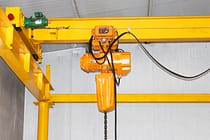
6.Suspension hoist installation:
The installation position of the eye must ensure that the hoist power connection port is facing the direction of the rotary arm support. Place the lifting eye of the electric hoist between the trolley lifting plates, insert the load bearing pin and fix it with the elastic pin. Make sure that the elastic pin opening is facing outwards, otherwise it will cause wear and will need to be replaced with a new elastic pin when the hoist is reassembled. For others, please refer to the manual of the electric hoist. All hoists must be marked on the side of the cantilever with the logo and rated lifting placard. The rated lifting capacity of the hoist must match the rated lifting capacity of the jib. Securely attach the rated lifting capacity placard and the trademark placard to the jib.
Note: The above installation sequence and method is not unique and allows users to adopt a better installation method.
Send Your Inquiry
- Email: sales@hndfcrane.com
- WhatsApp: +86 191 3738 6654
- Telegram: +86 191 3738 6654
- Tel: +86-373-581 8299
- Fax: +86-373-215 7000
- Add: Changnao Industrial District, Xinxiang City, Henan Province, China
 WeChat
- Overhead Cranes
- Double Girder Overhead Cranes
- Single Girder Overhead Cranes
- European Type Single Girder Overhead Cranes
- Explosion Proof Overhead Cranes
- Grab And Magnetic Overhead Cranes
- Monorail Cranes
- Foundry Overhead Cranes
- Workstation Cranes
- Jib Cranes
- Wall Mounted Jib Cranes
- Wall Travelling Jib Cranes
- Free Standing Jib Cranes
- Aluminum Jib Cranes: Lightweight, Smooth Rotating Arm for Easy Lifting
- Balance Jib Cranes: Efficient Light Lifting for Short Distance Mechanical Assembly
- Manual Free Standing Jib Cranes: Efficient Manual Lifting Solutions for Limited Space Operations
- Electric Free Standing Jib Cranes: Fully Electric Solution for High Capacity Fast Lifting
- Articulating Jib Cranes: Precision Lifting with Dual Arm Flexibility
- Gantry Cranes
- Double Girder Gantry Cranes
- Semi Gantry Cranes
- Single Girder Gantry Cranes
- Truss Gantry Cranes
- Container Gantry Cranes
- Adjustable Gantry Cranes
- Portable Gantry Cranes
- European Gantry Cranes
- Industries
- General Manufacturing
- Waste Handling
- Precast
- Power
- Stone
- Papermaking
- Metal Production
- Bridge Construction
- Port Cranes: For Container and Bulk Material Handling
- Overhead Cranes for Petroleum and Gas Industry: Enhance Operational Efficiency
- Marine Cranes for Efficient Cargo Loading on Ships
- Overhead Cranes for the Automotive Industry: Efficient Automation Solutions
- Electric Hoists
- Electric Wire Rope Hoists
- Electric Chain Hoists
- European Type Electric Hoists
- European Electric Chain Hoists: Smooth Operation, Low Noise, and Energy Efficiency
- Manual Lever Hoists: Ideal for Pulling and Lifting Tasks
- Hand Chain Hoists: Manual Lifting for Areas Without Power
- Low Headroom Electric Hoists: Compact Design for Maximum Space Efficiency
- Pneumatic Chain Hoists: Smooth Handling for Industrial Use
- Explosion Proof Manual Chain Hoists: Spark Resistant Copper Alloy Construction for Hazardous Areas
- Explosion Proof Electric Chain Hoists for Hazardous Area Lifting
- Contact Us
- Email: sales@hndfcrane.com
- WhatsApp: +86 191 3738 6654
- Telegram: +86 191 3738 6654
- Tel: +86-373-581 8299
-
