
-
Industries
-
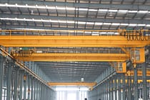
General Manufacturing
-
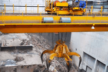
Waste Handling
-
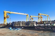
Precast
-
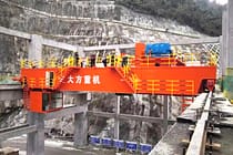
Power
-
Stone
-
Papermaking
-
Metal Production
-
Bridge Construction
-
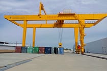
Port Cranes: For Container and Bulk Material Handling
-
Overhead Cranes for Petroleum and Gas Industry: Enhance Operational Efficiency
-

Marine Cranes for Efficient Cargo Loading on Ships
-
Overhead Cranes for the Automotive Industry: Efficient Automation Solutions
-
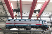
Overhead Crane Solutions for Railways: Track Laying, Rolling Stock Maintenance, and Container Handling
-
Overhead Cranes for Food and Beverages: Reliable Solutions for Efficient Handling
-
Overhead Cranes for Efficient Cement, Glass, Brick and Precast Concrete Manufacturing
-
Overhead Cranes for Aviation Industry: Aircraft Maintenance and Assembly
-
Aerospace Overhead Cranes: Precision Lifting for Rocket Launch and Transport
-
-
Products
-
Overhead Cranes
-
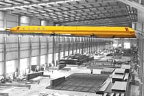
Single Girder Overhead Cranes
-
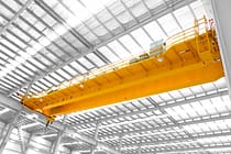
Double Girder Overhead Cranes
-
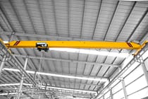
European Type Single Girder Overhead Cranes
-
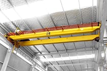
European Type Double Girder Overhead Cranes
-
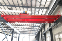
Explosion Proof Overhead Cranes
-
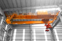
Grab And Magnetic Overhead Cranes
-
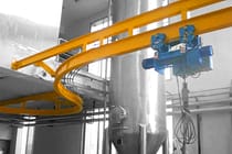
Monorail Cranes
-
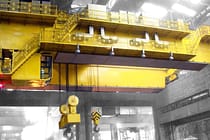
Foundry Overhead Cranes
-
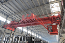
Insulation Overhead Cranes
-
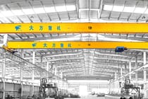
Low Headroom Overhead Cranes
-
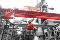
Grab Overhead Cranes
-

Ladle Overhead Cranes
-
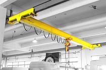
Underhung Overhead Cranes
-
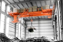
Electromagnetic Overhead Cranes
-
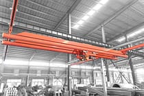
Workstation Cranes
-
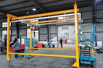
Free Standing Workstation Bridge Cranes
-
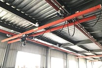
Ceiling Mounted Bridge Crane
-
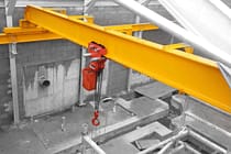
Manual Overhead Cranes
-
-
Gantry Cranes
-
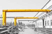
Semi Gantry Cranes
-
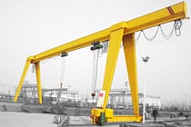
Single Girder Gantry Cranes
-
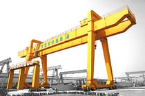
Double Girder Gantry Cranes
-
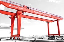
Container Gantry Cranes
-
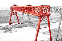
Truss Gantry Cranes
-
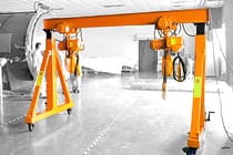
Adjustable Gantry Cranes
-
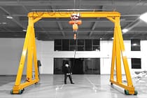
Portable Gantry Cranes
-
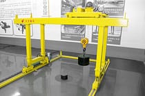
European Gantry Cranes
-
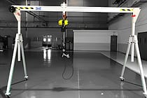
Aluminum Gantry Cranes
-
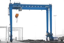
Rubber Tyred Container Gantry Cranes
-
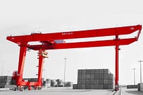
Rail Mounted Container Gantry Cranes
-
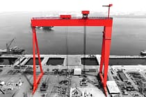
Shipyard Gantry Crane
-
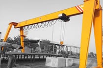
European Single Girder Gantry Cranes
-
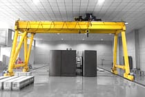
European Double Girder Gantry Cranes
-
- Jib Cranes
- Special Cranes
- Electric Hoists
- Transfer Carts
-
Overhead Cranes
-
Crane Parts
-
Grab Buckets
-
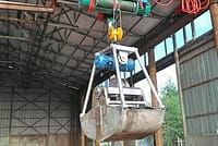
Electric Stainless Steel Grab Bucket
-
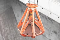
Mechanical Four Rope Orange Peel Grabs
-
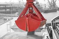
Mechanical Four Rope Clamshell Grabs Bucket
-
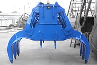
Electro Hydraulic Rectangular Grabs
-
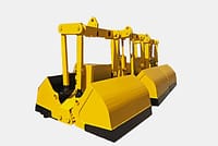
Electro hydraulic Clamshell Grabs
-
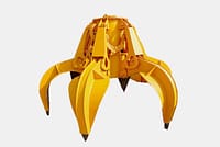
Electro Hydraulic Orange Peel Grabs,Hydraulic Cactus Grab
-
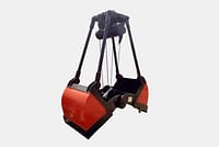
Electric Motor Grab
-
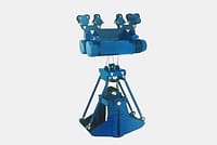
Electric Monorail Grab Bucket with Monorail Hoist
-
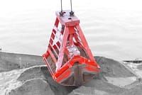
Remote Control Clamshell Grabs
-
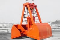
Mechanical Two Rope Clamshell Grabs
-

Timber Grabs
-
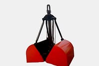
Single Rope Grab Bucket
-
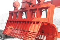
Trash Rack Cleaning Machines
-
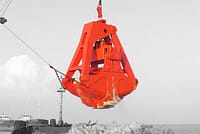
Dredging Grabs
-
Trimming Grabs
-
- Crane Spreader
-
Crane Spare Parts
-
Crane Sheaves
-
Wire Rope Sheaves
-
Crane Rope Drum
-
Crane Trolley
-
Electric Winch
-
Crane Operator Cabin
-
Overhead Crane Brakes
-
Overhead Crane Cables
-
Overhead Crane Rope Guides
-
Overhead Crane Conductors and Power Supply Lines
-
Overhead Crane Rails
-
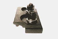
Overhead Crane Rail Clips
-
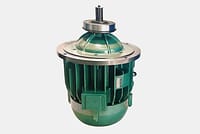
Overhead Crane Motors
-
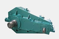
Overhead Crane Reducers
-
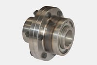
Couplings for Overhead Crane
-
- Crane Wheels
-
Grab Buckets
- Company
- Contact



-
Industries
-
General Manufacturing
-
Waste Handling
-
Precast
-
Power
-
Stone
-
Papermaking
-
Metal Production
-
Bridge Construction
-
Port Cranes: For Container and Bulk Material Handling
-
Overhead Cranes for Petroleum and Gas Industry: Enhance Operational Efficiency
-
Marine Cranes for Efficient Cargo Loading on Ships
-
Overhead Cranes for the Automotive Industry: Efficient Automation Solutions
-
Overhead Crane Solutions for Railways: Track Laying, Rolling Stock Maintenance, and Container Handling
-
Overhead Cranes for Food and Beverages: Reliable Solutions for Efficient Handling
-
Overhead Cranes for Efficient Cement, Glass, Brick and Precast Concrete Manufacturing
-
Overhead Cranes for Aviation Industry: Aircraft Maintenance and Assembly
-
Aerospace Overhead Cranes: Precision Lifting for Rocket Launch and Transport
-
-
Products
-
Overhead Cranes
-
Single Girder Overhead Cranes
-
Double Girder Overhead Cranes
-
European Type Single Girder Overhead Cranes
-
European Type Double Girder Overhead Cranes
-
Explosion Proof Overhead Cranes
-
Grab And Magnetic Overhead Cranes
-
Monorail Cranes
-
Foundry Overhead Cranes
-
Insulation Overhead Cranes
-
Low Headroom Overhead Cranes
-
Grab Overhead Cranes
-
Ladle Overhead Cranes
-
Underhung Overhead Cranes
-
Electromagnetic Overhead Cranes
-
Workstation Cranes
-
Free Standing Workstation Bridge Cranes
-
Ceiling Mounted Bridge Crane
-
Manual Overhead Cranes
-
-
Gantry Cranes
-
Semi Gantry Cranes
-
Single Girder Gantry Cranes
-
Double Girder Gantry Cranes
-
Container Gantry Cranes
-
Truss Gantry Cranes
-
Adjustable Gantry Cranes
-
Portable Gantry Cranes
-
European Gantry Cranes
-
Aluminum Gantry Cranes
-
Rubber Tyred Container Gantry Cranes
-
Rail Mounted Container Gantry Cranes
-
Shipyard Gantry Crane
-
European Single Girder Gantry Cranes
-
European Double Girder Gantry Cranes
-
- Jib Cranes
- Special Cranes
- Electric Hoists
- Transfer Carts
-
Overhead Cranes
-
Crane Parts
-
Grab Buckets
-
Electric Stainless Steel Grab Bucket
-
Mechanical Four Rope Orange Peel Grabs
-
Mechanical Four Rope Clamshell Grabs Bucket
-
Electro Hydraulic Rectangular Grabs
-
Electro hydraulic Clamshell Grabs
-
Electro Hydraulic Orange Peel Grabs,Hydraulic Cactus Grab
-
Electric Motor Grab
-
Electric Monorail Grab Bucket with Monorail Hoist
-
Remote Control Clamshell Grabs
-
Mechanical Two Rope Clamshell Grabs
-
Timber Grabs
-
Single Rope Grab Bucket
-
Trash Rack Cleaning Machines
-
Dredging Grabs
-
Trimming Grabs
-
- Crane Spreader
-
Crane Spare Parts
-
Crane Sheaves
-
Wire Rope Sheaves
-
Crane Rope Drum
-
Crane Trolley
-
Electric Winch
-
Crane Operator Cabin
-
Overhead Crane Brakes
-
Overhead Crane Cables
-
Overhead Crane Rope Guides
-
Overhead Crane Conductors and Power Supply Lines
-
Overhead Crane Rails
-
Overhead Crane Rail Clips
-
Overhead Crane Motors
-
Overhead Crane Reducers
-
Couplings for Overhead Crane
-
- Crane Wheels
-
Grab Buckets
- Company
- Contact



Crane Design Terminology: A Beginner's Guide to Essential Terms
Table of Contents
Crane design terminology forms the basis for reading engineering drawings, performing design calculations, and communicating technical proposals. This guide introduces common terms covering crane parameters, duty classes, metal structures, loads, and performance indicators.
Key Crane Design Terminology: Parameters and Duty Classes
Crane mechanism parameters describe the operating performance of lifting machinery and provide a basis for design and equipment selection. A crane duty class considers the utilization of lifting capacity and time, as well as the number of working cycles.
1. Rated Lifting Capacity Gn
Rated lifting capacity is the total weight of the load or material that a crane can lift, together with detachable lifting attachments (excluding container spreaders) or accessories such as grabs, electromagnetic lifting devices, and lifting beams. For variable-radius cranes, such as tower cranes, truck cranes, and portal cranes, rated lifting capacity changes with the working radius. The nominal rated lifting capacity is the maximum rated capacity permitted under safe working conditions at the minimum radius.
In ordinary usage, “lifting capacity” generally means rated lifting capacity.
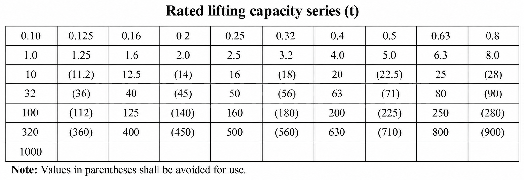
To support series production and standardization, a rated-capacity series standard has been established (Table 1-1). The source cites GB783-87 and gives the unit as t. For newly designed lifting machinery, the rated lifting capacity of the crane and auxiliary hoisting mechanism should conform to the standard series values. Equipment with special performance should also conform to, or remain as close as possible to, the standard series values.
2. Span S
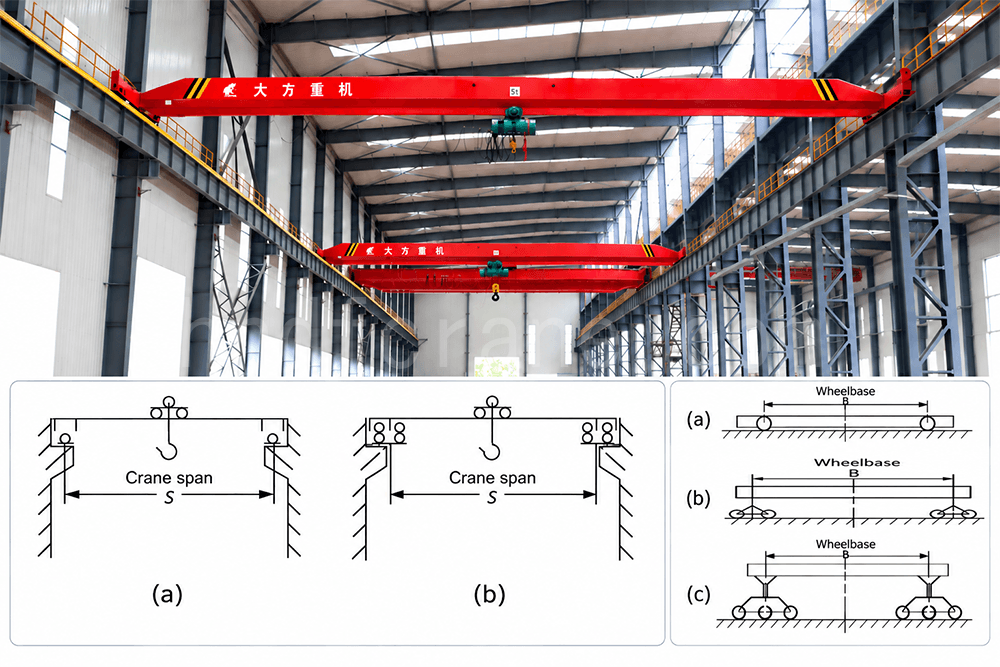
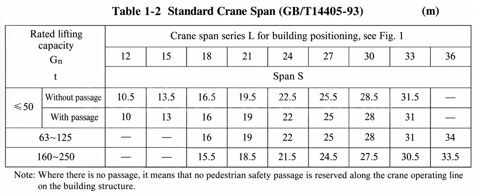
For a bridge crane, span is the horizontal distance between the centerlines of the crane's bridge-travel rails. It is represented by S, although L was commonly used in the past, and is measured in metres (m). Electric bridge crane spans have a national standard series (source Table 1-2). Figure 1-1 illustrates crane span. The span of a bridge crane depends on the building span Sc; in the span series, the increment is generally 3 m.
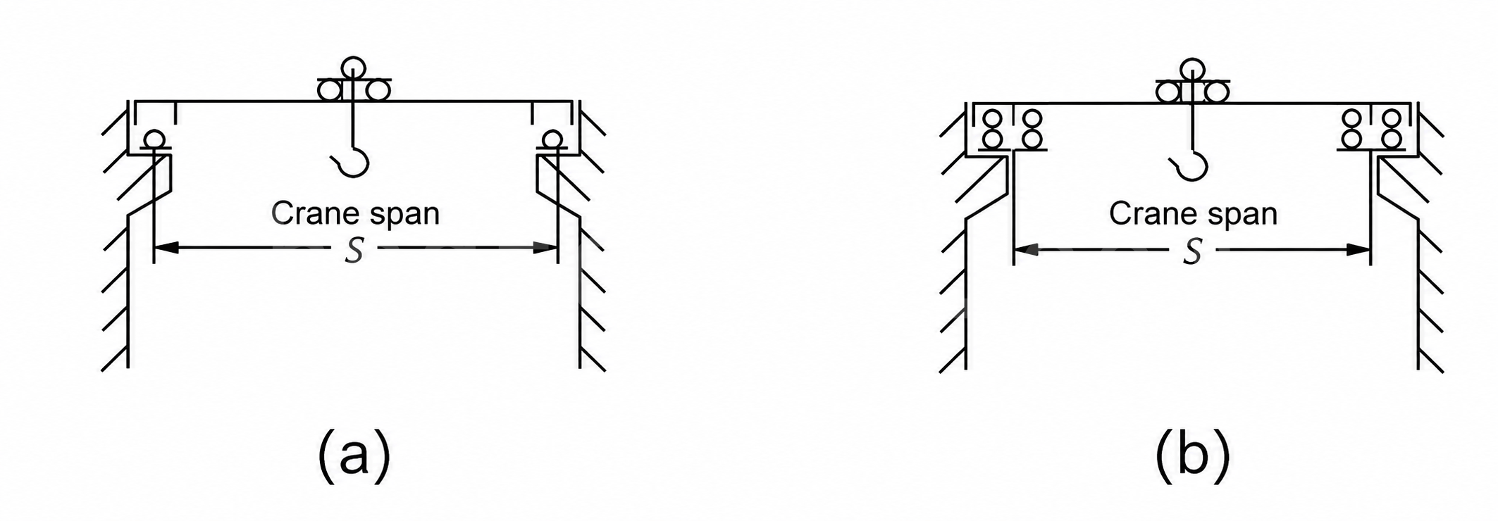
Figure 1-1 includes (a) crane span and (b) the span of a crane with two rails.
3. Gauge K
Gauge, also called wheel track, is defined as follows:
- For a trolley, it is the distance between the centerlines of the trolley rails.
- For a jib-type crane, it is the distance between the rail centerlines or between the centerlines of the running-wheel treads.
4. Wheelbase B
Wheelbase, also called axle spacing, is the distance between the support centerlines of the crane or trolley along the longitudinal travel direction. The measurement of wheelbase B depends on the arrangement of the supporting wheels.
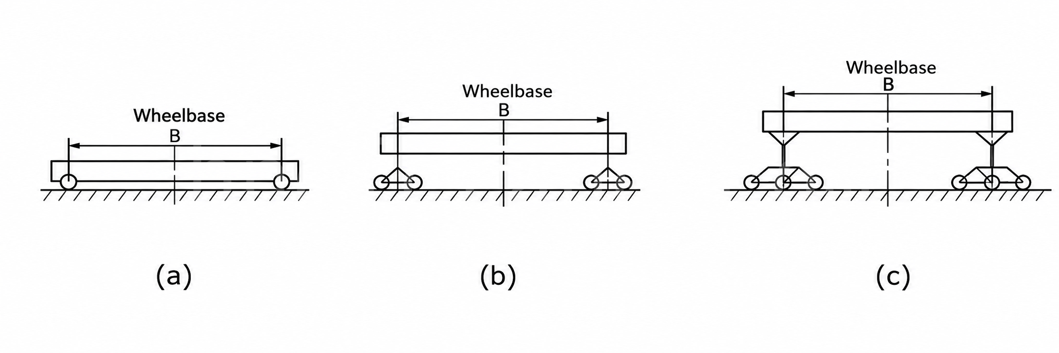
5. Lifting Height H, Lowering Depth h, and Lifting Range D
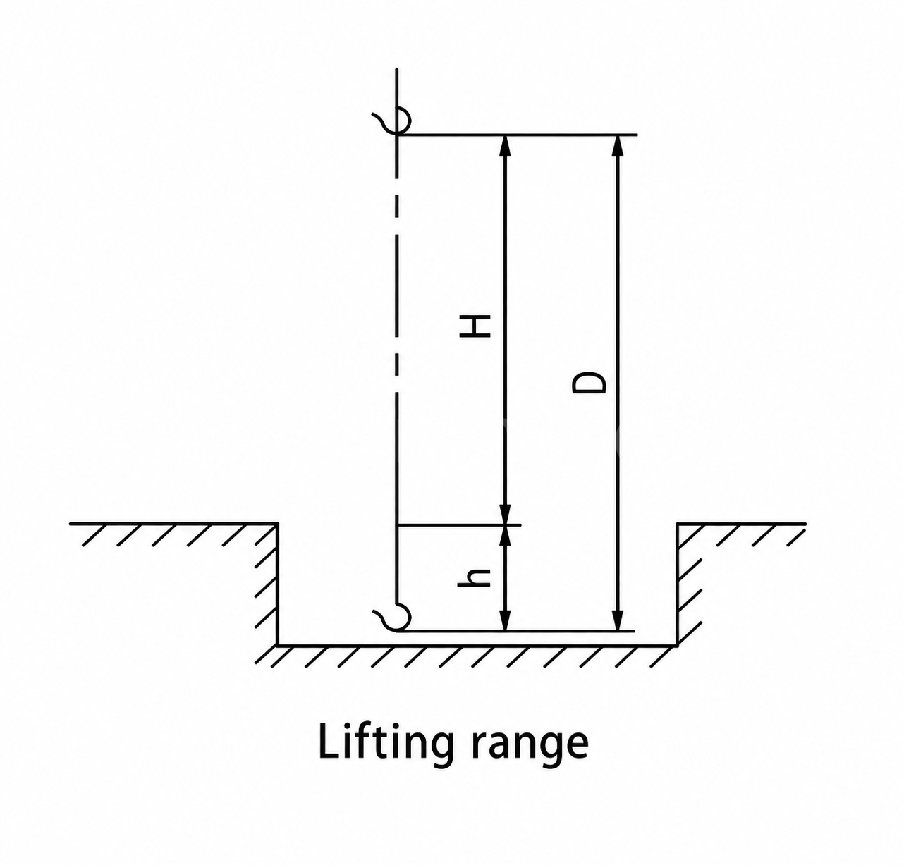
The source defines the relevant vertical distances using the highest and lowest working positions of the lifting attachment and gives:
D = H + h
Where there is no lowering depth, lifting range D equals lifting height H. Lifting height and lowering depth are measured using the centre of the hook bowl as the reference point. For other lifting attachments, such as grabs, the lowest point in the closed position is used as the reference.
6. Mechanism Operating Speeds
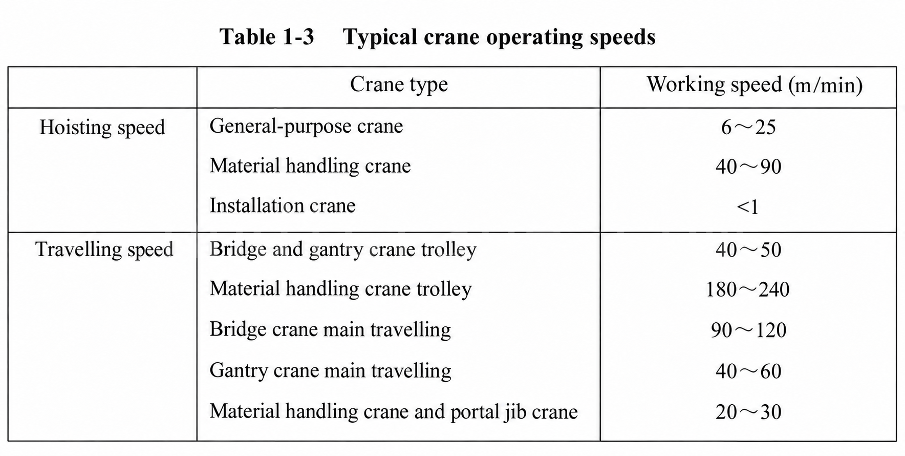
Mechanism operating speeds vary according to the crane mechanism:
- Lifting and lowering speed Vn: the vertical displacement speed of the rated load in a steady operating state, measured in m/min.
- Crane or bridge-travel speed VR': the travel speed of the crane carrying its rated load on a horizontal surface or rail in a steady operating state, measured in m/min.
- Trolley-travel speed Vt': the speed of a trolley carrying its rated load along a horizontal rail in a steady operating state, measured in m/min.
7. Wheel Load
Wheel load is the maximum vertical pressure exerted on the crane wheels by the bridge self-weight, together with the trolley self-weight and rated lifting capacity when the trolley is at its limiting position. It is an important basis for the design of the travel mechanism and rails.
8. Duty Class
Crane duty class is divided according to utilization class—the total number of working cycles over the design life—and load state. It indicates how demanding the crane's work is, including how busy it is over time and how often it handles full loads.
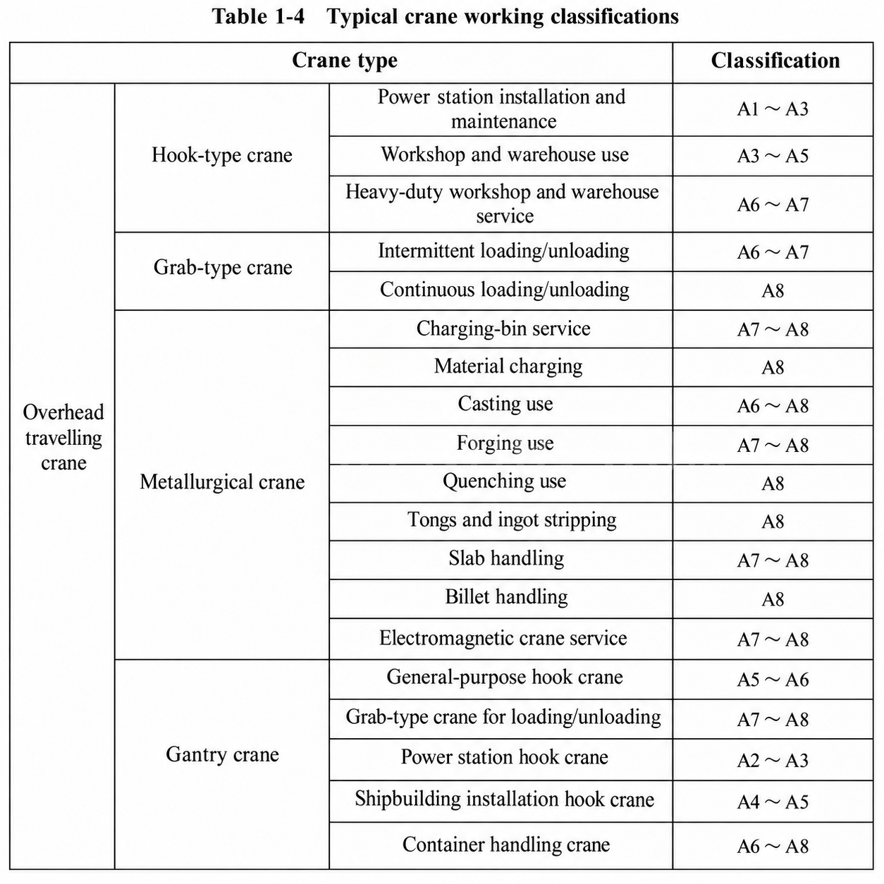
The source divides duty classes into A1–A8. Its approximate comparison is A1–A4 for light duty, A5–A6 for medium duty, A7 for heavy duty, and A8 for extra-heavy duty. Source Table 1-4 lists examples of crane duty classes.
Common Terms for Crane Metal Structures and Components
1. Crane Metal Structure
A crane metal structure, also called a crane steel structure, is a structure capable of carrying the various loads of a crane. It consists of steel plates and sections formed from metal materials and assembled in a defined structural arrangement using welding, riveting, bolting, and other connection methods.
Crane metal structures consist of load-bearing members, non-load-bearing members, and connection sections. Main girders, end girders, and legs are load-bearing members and require strength, stiffness, and stability calculations. Walkways, railings, and ladders are non-load-bearing members; the source states that they do not require strength, stiffness, and stability calculations, but that safety, ease of use, and ergonomics should be considered. Connections mainly use welding and bolting, while riveting is now rarely used.
2. Typical Metal-Structure Types
Typical types include bridge structures, gantries, towers, and jibs. Crane metal structures are made from members, plates, and sections that form basic members such as main girders, end girders, and legs. Different members form basic crane structures such as bridges, gantries, towers, and jibs.
3. Common Structural and Component Terms
- Main girder: The primary load-bearing member of an overhead or gantry crane, carrying the lifting load.
- Leg: A support member of a gantry crane or truck crane that helps maintain overall operating stability.
- Jib: A fixed or telescopic arm on a jib-type crane used for lifting loads and adjusting the working radius.
- Hoisting mechanism: The mechanism that raises and lowers loads vertically, consisting of a motor, gearbox, drum, brake, hook, and other components.
- Travel mechanism: The mechanism that moves the complete crane or trolley; it may be rail-mounted or non-rail-mounted.
- Slewing mechanism: The mechanism that rotates a jib around a vertical axis, commonly used on truck cranes, crawler cranes, and tower cranes.
- Brake: A braking device used for stopping, speed limiting, and safety holding.
- Limit switch: A safety device that limits lifting height, travel distance, or slewing angle to prevent overtravel.
- Overload limiter: A safety device that automatically cuts lifting power when the lifted load exceeds the rated value.
Load and Force Terms
1. Regular Loads
Regular loads occur frequently during normal crane operation. They include gravity loads, inertial loads produced when driving or braking accelerates or decelerates the crane, and loads caused by displacement or deformation of the crane steel structure. These loads should be considered when calculating and checking against strength failure, elastic instability, and fatigue failure.
Regular loads include:
- Self-weight load PG: The gravitational force of the crane's steel structure, mechanisms, electrical equipment, and other masses.
- Rated lifting load PQ: The gravitational force of the total lifted mass when lifting the rated capacity. When the lifting capacity is large, the weight of the lifting attachment and wire rope should be included.
- Horizontal travel inertial load PH: The horizontal inertial force produced by the crane's or trolley's own mass and lifted mass when travelling longitudinally or transversely and accelerating or braking in a horizontal plane.
2. Accidental Loads
Accidental loads are loads that do not occur frequently during normal operation but may arise occasionally. They mainly include the following types:
- Horizontal lateral load from skewing Ps: A load caused by the guiding reaction at a guiding device, such as a wheel flange or horizontal guide wheel, when the crane or trolley skews during longitudinal or transverse travel.
- Grade load Pp: The resistance experienced when the crane or trolley travels uphill along its running rail. The source wording “along s running rail” appears to contain a textual error and requires technical review.
- In-service wind load Pw: The maximum wind force that an outdoor crane should withstand while operating. The source also mentions ice, snow, and temperature loads.
3. Special Loads
Special loads are loads that occur under exceptional conditions when the crane is not operating normally or is out of service. They mainly include the following types:
- Collision load Pc: A load generated when two adjacent cranes on the same rail collide, or when a crane collides with a buffer stop at the end of the rail.
- Horizontal overturning load Psl: For example, in a stacker crane, an object or load-handling device moving inside a rigid lifting guide frame, or the lower end of the rigid guide frame, may collide with an obstacle and generate a horizontal force that tends to overturn the crane or trolley.
- Seismic load PE: A load caused by an earthquake and acting on a hoist-type crane.
- Out-of-service wind load: The maximum wind force that the crane can withstand while out of service, measured in N.
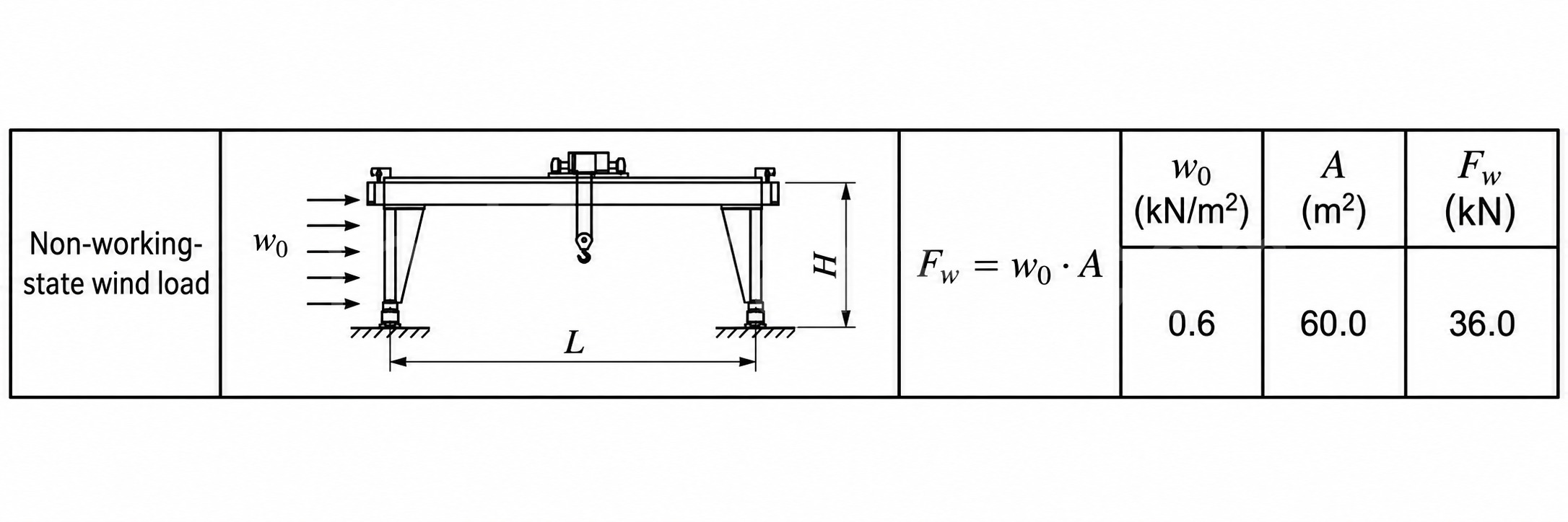
Other loads may occur in specific situations, such as process loads. Fatigue load is a cyclic alternating load experienced by the structure during repeated crane operation and affects equipment service life.
Performance-Indicator Terms
- Strength, including fatigue-strength verification: The ability of a member to avoid failure under external forces. Strength includes tensile and compressive strength, bending strength, shear strength, and bearing or crushing strength.
- Stiffness: The ability to limit member deformation under external forces. It includes static stiffness in the vertical and horizontal directions, as well as dynamic stiffness related to use.
- Stability: The ability to resist loss of stability under external forces. It includes overall anti-overturning capacity, global member stability, and local stability.
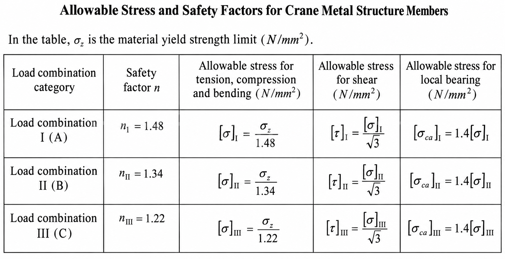
- Safety factor: The safety margin reserved in design, defined here as the ratio of structural load-bearing capacity to actual loading. It must meet applicable code requirements.
- Allowable stress: The maximum stress value that the applicable code permits the structural material to withstand.
Summary
These terms are basic and frequently used in crane design. They support drawing preparation, parameter calculations, technical proposal discussions, and further study of structural design and code application.

I am Cindy, with 10 years of working experience in the crane industry and accumulated a wealth of professional knowledge. I have chosen the satisfying cranes for 500+ customers. If you have any needs or questions about cranes, please feel free to contact me, I will use my expertise and practical experience to help you solve the problem!
Send Your Inquiry
- Email: sales@hndfcrane.com
- WhatsApp: +86 191 3738 6654
- Telegram: +86 191 3738 6654
- Tel: +86-373-581 8299
- Fax: +86-373-215 7000
- Add: Changnao Industrial District, Xinxiang City, Henan Province, China
 WeChat
- Overhead Cranes
- Double Girder Overhead Cranes
- Single Girder Overhead Cranes
- European Type Single Girder Overhead Cranes
- Explosion Proof Overhead Cranes
- Grab And Magnetic Overhead Cranes
- Monorail Cranes
- Foundry Overhead Cranes
- Workstation Cranes
- Jib Cranes
- Wall Mounted Jib Cranes
- Wall Travelling Jib Cranes
- Free Standing Jib Cranes
- Aluminum Jib Cranes: Lightweight, Smooth Rotating Arm for Easy Lifting
- Balance Jib Cranes: Efficient Light Lifting for Short Distance Mechanical Assembly
- Manual Free Standing Jib Cranes: Efficient Manual Lifting Solutions for Limited Space Operations
- Electric Free Standing Jib Cranes: Fully Electric Solution for High Capacity Fast Lifting
- Articulating Jib Cranes: Precision Lifting with Dual Arm Flexibility
- Gantry Cranes
- Double Girder Gantry Cranes
- Semi Gantry Cranes
- Single Girder Gantry Cranes
- Truss Gantry Cranes
- Container Gantry Cranes
- Adjustable Gantry Cranes
- Portable Gantry Cranes
- European Gantry Cranes
- Industries
- General Manufacturing
- Waste Handling
- Precast
- Power
- Stone
- Papermaking
- Metal Production
- Bridge Construction
- Port Cranes: For Container and Bulk Material Handling
- Overhead Cranes for Petroleum and Gas Industry: Enhance Operational Efficiency
- Marine Cranes for Efficient Cargo Loading on Ships
- Overhead Cranes for the Automotive Industry: Efficient Automation Solutions
- Electric Hoists
- Electric Wire Rope Hoists
- Electric Chain Hoists
- European Type Electric Hoists
- European Electric Chain Hoists: Smooth Operation, Low Noise, and Energy Efficiency
- Manual Lever Hoists: Ideal for Pulling and Lifting Tasks
- Hand Chain Hoists: Manual Lifting for Areas Without Power
- Low Headroom Electric Hoists: Compact Design for Maximum Space Efficiency
- Pneumatic Chain Hoists: Smooth Handling for Industrial Use
- Explosion Proof Manual Chain Hoists: Spark Resistant Copper Alloy Construction for Hazardous Areas
- Explosion Proof Electric Chain Hoists for Hazardous Area Lifting
- Contact Us
- Email: sales@hndfcrane.com
- WhatsApp: +86 191 3738 6654
- Telegram: +86 191 3738 6654
- Tel: +86-373-581 8299
-