
-
Industries
-

General Manufacturing
-
Waste Handling
-

Precast
-
Power
-

Stone
-

Papermaking
-
Metal Production
-
Bridge Construction
-

Port Cranes: For Container and Bulk Material Handling
-

Overhead Cranes for Petroleum and Gas Industry: Enhance Operational Efficiency
-

Marine Cranes for Efficient Cargo Loading on Ships
-

Overhead Cranes for the Automotive Industry: Efficient Automation Solutions
-
Overhead Crane Solutions for Railways: Track Laying, Rolling Stock Maintenance, and Container Handling
-

Overhead Cranes for Food and Beverages: Reliable Solutions for Efficient Handling
-

Overhead Cranes for Efficient Cement, Glass, Brick and Precast Concrete Manufacturing
-
Overhead Cranes for Aviation Industry: Aircraft Maintenance and Assembly
-

Aerospace Overhead Cranes: Precision Lifting for Rocket Launch and Transport
-
-
Products
-
Overhead Cranes
-
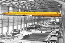
Single Girder Overhead Cranes
-
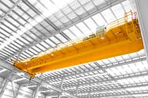
Double Girder Overhead Cranes
-
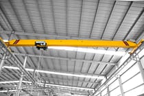
European Type Single Girder Overhead Cranes
-
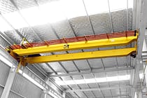
European Type Double Girder Overhead Cranes
-
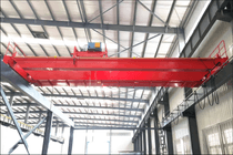
Explosion Proof Overhead Cranes
-
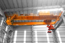
Grab And Magnetic Overhead Cranes
-

Monorail Cranes
-

Foundry Overhead Cranes
-
Insulation Overhead Cranes
-

Low Headroom Overhead Cranes
-

Grab Overhead Cranes
-

Ladle Overhead Cranes
-
Underhung Overhead Cranes
-
Electromagnetic Overhead Cranes
-
Workstation Cranes
-
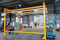
Free Standing Workstation Bridge Cranes
-
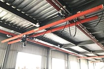
Ceiling Mounted Bridge Crane
-
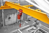
Manual Overhead Cranes
-
-
Gantry Cranes
-

Semi Gantry Cranes
-
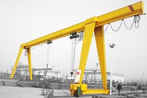
Single Girder Gantry Cranes
-

Double Girder Gantry Cranes
-
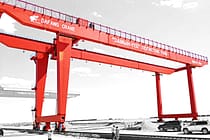
Container Gantry Cranes
-
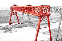
Truss Gantry Cranes
-
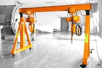
Adjustable Gantry Cranes
-
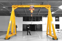
Portable Gantry Cranes
-
European Gantry Cranes
-

Aluminum Gantry Cranes
-
Rubber Tyred Container Gantry Cranes
-

Rail Mounted Container Gantry Cranes
-

Shipyard Gantry Crane
-
European Single Girder Gantry Cranes
-

European Double Girder Gantry Cranes
-
- Jib Cranes
- Special Cranes
- Electric Hoists
- Transfer Carts
-
Overhead Cranes
-
Crane Parts
-
Grab Buckets
-
Electric Stainless Steel Grab Bucket
-
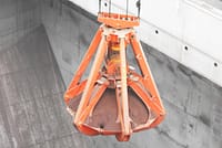
Mechanical Four Rope Orange Peel Grabs
-

Mechanical Four Rope Clamshell Grabs Bucket
-
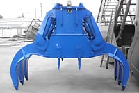
Electro Hydraulic Rectangular Grabs
-
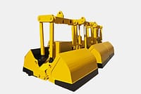
Electro hydraulic Clamshell Grabs
-
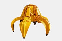
Electro Hydraulic Orange Peel Grabs,Hydraulic Cactus Grab
-
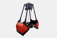
Electric Motor Grab
-
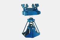
Electric Monorail Grab Bucket with Monorail Hoist
-
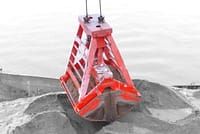
Remote Control Clamshell Grabs
-
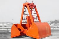
Mechanical Two Rope Clamshell Grabs
-

Timber Grabs
-

Single Rope Grab Bucket
-
Trash Rack Cleaning Machines
-

Dredging Grabs
-
Trimming Grabs
-
- Crane Spreader
-
Crane Spare Parts
-
Crane Sheaves
-
Wire Rope Sheaves
-
Crane Rope Drum
-
Crane Trolley
-
Electric Winch
-

Crane Operator Cabin
-
Overhead Crane Brakes
-
Overhead Crane Cables
-
Overhead Crane Rope Guides
-
Overhead Crane Conductors and Power Supply Lines
-

Overhead Crane Rails
-
Overhead Crane Rail Clips
-
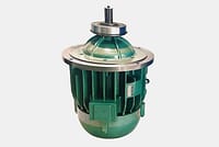
Overhead Crane Motors
-
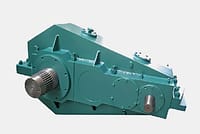
Overhead Crane Reducers
-
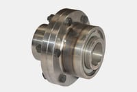
Couplings for Overhead Crane
-
- Crane Wheels
-
Grab Buckets
- Company
- Contact











-
Industries
-
General Manufacturing
-
Waste Handling
-
Precast
-
Power
-
Stone
-
Papermaking
-
Metal Production
-
Bridge Construction
-
Port Cranes: For Container and Bulk Material Handling
-
Overhead Cranes for Petroleum and Gas Industry: Enhance Operational Efficiency
-
Marine Cranes for Efficient Cargo Loading on Ships
-
Overhead Cranes for the Automotive Industry: Efficient Automation Solutions
-
Overhead Crane Solutions for Railways: Track Laying, Rolling Stock Maintenance, and Container Handling
-
Overhead Cranes for Food and Beverages: Reliable Solutions for Efficient Handling
-
Overhead Cranes for Efficient Cement, Glass, Brick and Precast Concrete Manufacturing
-
Overhead Cranes for Aviation Industry: Aircraft Maintenance and Assembly
-
Aerospace Overhead Cranes: Precision Lifting for Rocket Launch and Transport
-
-
Products
-
Overhead Cranes
-
Single Girder Overhead Cranes
-
Double Girder Overhead Cranes
-
European Type Single Girder Overhead Cranes
-
European Type Double Girder Overhead Cranes
-
Explosion Proof Overhead Cranes
-
Grab And Magnetic Overhead Cranes
-
Monorail Cranes
-
Foundry Overhead Cranes
-
Insulation Overhead Cranes
-
Low Headroom Overhead Cranes
-
Grab Overhead Cranes
-
Ladle Overhead Cranes
-
Underhung Overhead Cranes
-
Electromagnetic Overhead Cranes
-
Workstation Cranes
-
Free Standing Workstation Bridge Cranes
-
Ceiling Mounted Bridge Crane
-
Manual Overhead Cranes
-
-
Gantry Cranes
-
Semi Gantry Cranes
-
Single Girder Gantry Cranes
-
Double Girder Gantry Cranes
-
Container Gantry Cranes
-
Truss Gantry Cranes
-
Adjustable Gantry Cranes
-
Portable Gantry Cranes
-
European Gantry Cranes
-
Aluminum Gantry Cranes
-
Rubber Tyred Container Gantry Cranes
-
Rail Mounted Container Gantry Cranes
-
Shipyard Gantry Crane
-
European Single Girder Gantry Cranes
-
European Double Girder Gantry Cranes
-
- Jib Cranes
- Special Cranes
- Electric Hoists
- Transfer Carts
-
Overhead Cranes
-
Crane Parts
-
Grab Buckets
-
Electric Stainless Steel Grab Bucket
-
Mechanical Four Rope Orange Peel Grabs
-
Mechanical Four Rope Clamshell Grabs Bucket
-
Electro Hydraulic Rectangular Grabs
-
Electro hydraulic Clamshell Grabs
-
Electro Hydraulic Orange Peel Grabs,Hydraulic Cactus Grab
-
Electric Motor Grab
-
Electric Monorail Grab Bucket with Monorail Hoist
-
Remote Control Clamshell Grabs
-
Mechanical Two Rope Clamshell Grabs
-
Timber Grabs
-
Single Rope Grab Bucket
-
Trash Rack Cleaning Machines
-
Dredging Grabs
-
Trimming Grabs
-
- Crane Spreader
-
Crane Spare Parts
-
Crane Sheaves
-
Wire Rope Sheaves
-
Crane Rope Drum
-
Crane Trolley
-
Electric Winch
-
Crane Operator Cabin
-
Overhead Crane Brakes
-
Overhead Crane Cables
-
Overhead Crane Rope Guides
-
Overhead Crane Conductors and Power Supply Lines
-
Overhead Crane Rails
-
Overhead Crane Rail Clips
-
Overhead Crane Motors
-
Overhead Crane Reducers
-
Couplings for Overhead Crane
-
- Crane Wheels
-
Grab Buckets
- Company
- Contact



Single Girder Overhead Crane Installation: Key Inspection Points and Technical Requirements
Table of Contents
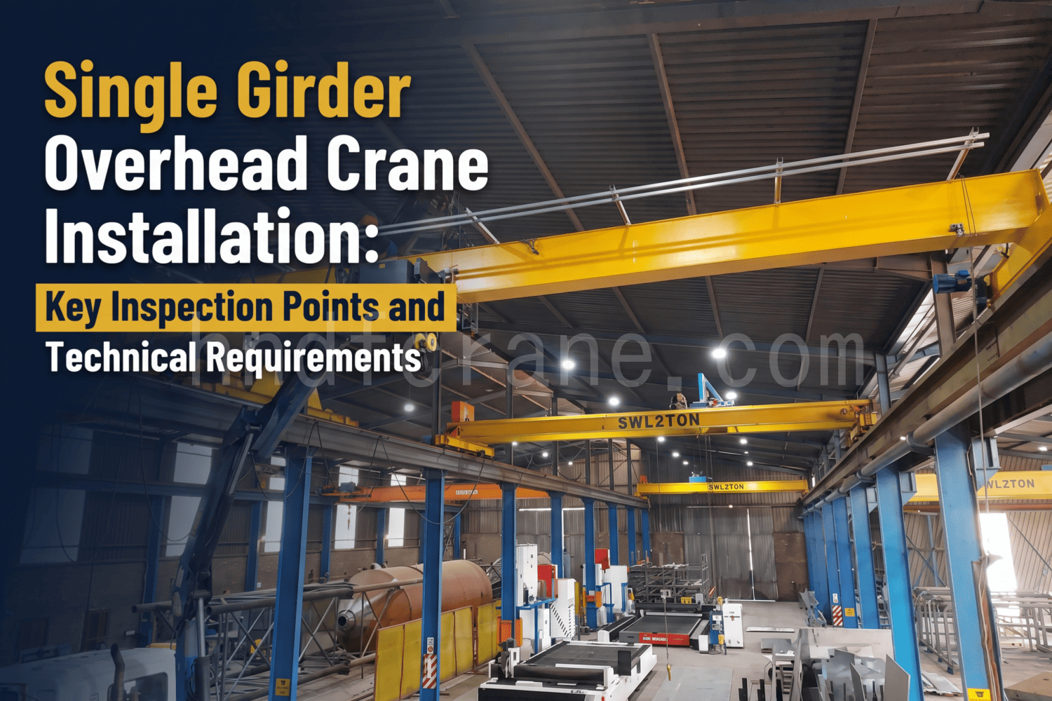
Single girder overhead crane installation may seem simple — after the main girder, end carriages, electric hoist, and other major components are assembled, the crane is lifted onto the runway rails.
However, we have seen many cases of “installed, but not installed correctly”: the crane running off track and causing rail biting, the hoist swinging from side to side during operation, or bearings making abnormal noises after less than three months of operation. After inspection, the problems are almost never caused by the components themselves. The issues usually come from those installation details that were considered “good enough.”
Therefore, this article does not teach you how to install the crane step by step. Instead, it focuses on the key technical requirements and important inspection points during the single girder overhead crane installation process, such as rail installation, bridge assembly, and electric hoist installation. For example, the height difference at rail joints should be ≤1 mm, and the clearance between the hoist wheel flange and the I-beam should be 3–5 mm.
Preparation Before Installation — Unpacking Inspection
The first thing the installation team should do after arriving at the site is not to move tools, but to unpack and inspect the equipment.
According to the packing list, check each item one by one: whether the quantity of components is correct, whether there is any damage caused during transportation, and whether all documents (such as certificates of conformity, electrical diagrams, and drawings) are complete.
After checking the delivered components, there is another step that is even more important — inspecting the appearance of the metal structural parts.
Check whether the main girder has been twisted, bent, or impacted during transportation. If these defects are not discovered and corrected on the ground before installation on the runway rails, the cost of handling them after lifting will increase significantly.
Handling and Storage Details
During single girder overhead crane unloading and handling, the main concerns are twisting, bending, and impact damage. The correct methods are:
- There should be at least two lifting points, preferably located at both ends of the bridge frame, which are the connection areas between the main girder and end carriages. These areas have stronger structures and more reasonable load distribution.
- Cushioning materials must be placed at the lifting points. If steel wire ropes directly contact and damage the paint surface of the steel structure, rusting will only be a matter of time.
- During storage, the crane components must be placed flat and properly supported. Wooden blocks should be evenly placed under the stiffening plates at the variable-section areas of the main girder. The main girder must not be left unsupported.
Runway Rail Installation — A 1 mm Tolerance Difference Can Cause 10 Times More Wear

The runway rail is the “road” of the crane. If the road is uneven, even a good vehicle will run poorly.
For single girder overhead cranes, the tolerance control of runway rail installation directly affects the service life of the travel mechanism. Problems such as wheel flange biting, motor overload, and abnormal running noise are mostly caused by rail installation issues.
Span Tolerance
According to the current standard GB/T 10183.1-2018, the allowable deviation of crane runway span is as follows:
| Span S | Allowable deviation ΔS |
|---|---|
| S ≤ 10 m | ±3 mm |
| S > 10 m | ±[3 + 0.25 × (S − 10)] mm, maximum not exceeding ±15 mm |
For example: For a single girder overhead crane with a span of 20 m, the allowable runway span deviation is:±[3 + 0.25 × (20−10)] = ±5.5 mm. This value is not large, but it must be controlled within the allowable range. Once the deviation exceeds the limit, the friction between the wheel flange and the rail side will increase significantly.
Rail Joint Treatment
There are two methods for rail joints: straight joints and 45° inclined joints. Inclined joints allow the wheels to pass through the joint more smoothly.
The three key values at the rail joint are:
- Joint gap: 1–2 mm
- Lateral misalignment: ≤1 mm
- Height difference: ≤1 mm
If any of these three values exceeds the limit, the wheel will “jump” when passing through the joint.
For a fully loaded 10-ton crane passing through this joint hundreds of times every day, the accumulated impact force will cause increasing damage to the wheel bearings.
Control Within the Entire Rail Length
In addition to joints and span accuracy, several other indicators that are often overlooked are equally important:
- The height difference between the two rails at each section along the span direction: ≤15 mm. Exceeding this value means that the crane travel mechanism will operate with a slight tilt throughout the entire travel distance, causing uneven wheel loading.
- Within the total rail length, the lateral limit deviation is ±10 mm. The allowable horizontal bending deviation along the rail length is ≤±1 mm for every 2 m measuring section.
The easiest point to overlook is that: The rail ends must be equipped with end stops by welding, and the end stops must make even contact with the crane buffers.
Bridge Frame Assembly — The Connection Between Main Girder and End Carriages Is Not Simply “Tightening Bolts”
The main girder and end carriages are connected using detachable bolted connections. Although they are separated during transportation from the factory, the installation process at the site requires assembling the complete bridge frame before lifting, rather than assembling individual parts at height.
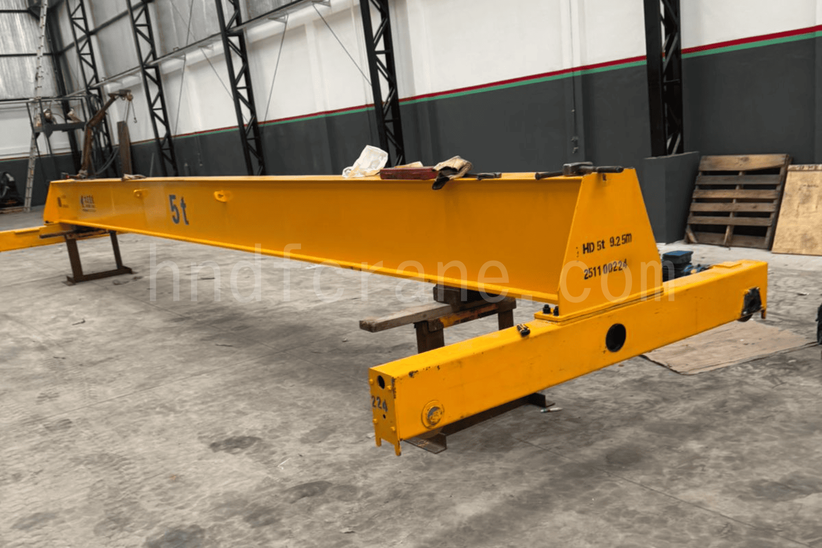
According to the drawing, place the main girder on two parallel support frames at the same horizontal level. The support frames should be positioned under the stiffening plates at the variable-section areas on both ends of the main girder, and the level should be adjusted properly.
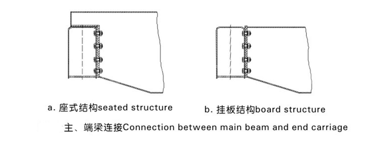
After positioning, the three key steps are:
- Clean the connection surfaces: The connection surfaces between the main girder and end carriages may have dust or contaminants due to transportation and storage. If the surfaces are not cleaned before tightening the bolts, even a high bolt preload cannot achieve the designed friction force.
- Position according to the connection plate locating shoulders: The locating shoulder is the built-in positioning reference of the structure. Using it for alignment is faster and more accurate than measuring manually with a ruler.
- Tighten the high-strength bolts symmetrically: This is not simply tightening the bolts randomly. The bolts must be tightened symmetrically from top to bottom and left to right, gradually and evenly. If one side is tightened completely first, the other side may lift, causing the bridge frame diagonal dimensions to deviate.
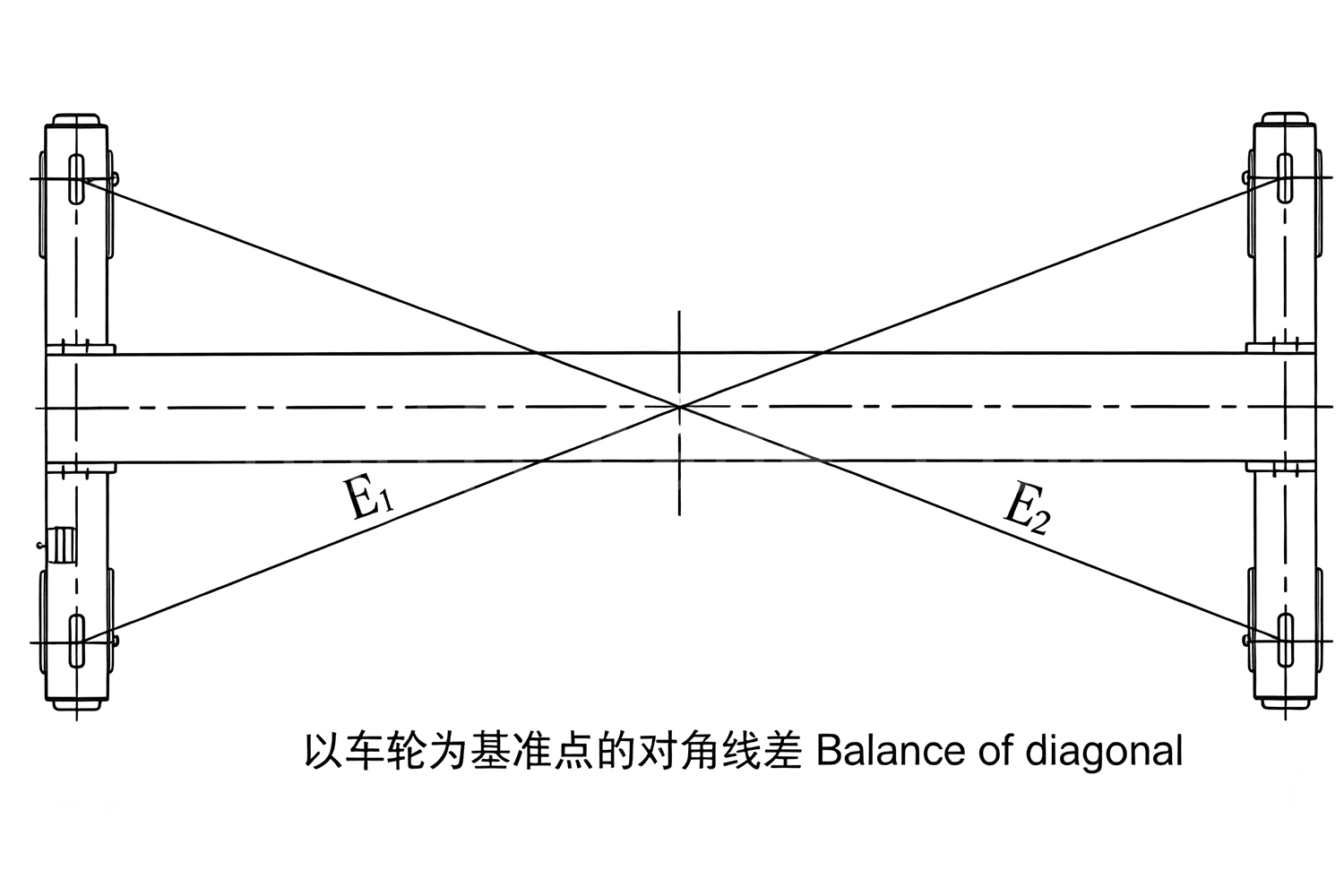
After tightening is completed, the bridge frame diagonal deviation is one of our mandatory inspection items. If the diagonals of the bridge frame are not equal, the crane will inevitably run off track after being installed on the rails. Measured from the reference points for wheel installation: |E1-E2| ≤ 5 mm
Electric Hoist Installation — A 3–5 mm Clearance Determines Whether the Hoist Runs Smoothly
After the single girder overhead crane main girder is lifted to an appropriate height, install the electric hoist directly onto the I-beam rail.
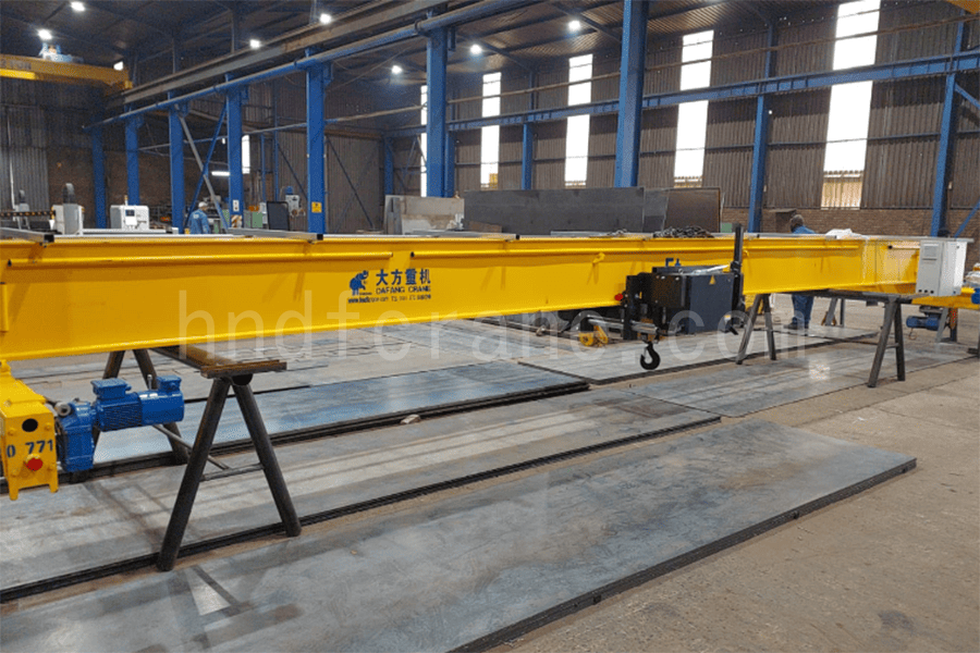
The clearance between the inner side of the hoist wheel flange and the lower flange of the I-beam rail should be 3–5 mm.
Although this value seems small, it directly affects:
- Clearance too small (<3 mm): The wheel flange will rub against the I-beam during hoist operation, causing high resistance, increased noise, and faster wear.
- Clearance too large (>5 mm): The hoist will swing from side to side during operation, especially during starting and braking, resulting in poor stability.
Electrical Installation — Inspection Before Installation
The installation of electrical equipment and wiring shall be carried out according to the supplied electrical schematic diagram, wiring diagram, and general electrical equipment drawing. Before installation, the electrical equipment and components shall be inspected:
- Appearance and specification inspection: Electrical equipment and components shall be free from defects and operate flexibly without jamming or looseness. The model, specifications, and contact closing sequence must comply with the requirements shown on the drawings. Any components requiring adjustment shall be adjusted in advance according to the drawings.
- Insulation resistance measurement: Use a megohmmeter to measure the insulation resistance of electrical components such as motors, hydraulic brakes, carbon brushes, contactors, relays, and resistors one by one. Components with insulation resistance below 1 MΩ must be dried and can only be installed and used after passing inspection.
- Check the pressure between the motor carbon brushes and slip rings. The pressure of all carbon brushes on the same motor must be consistent. The carbon brushes shall fully contact the slip rings. When grinding the carbon brushes, do not round their edges.
- Check the contact pressure of controllers, contactors, and relay contacts to ensure it meets their respective requirements. If the pressure is too high or too low, it shall be adjusted.
Electrical Control Cabinet Installation
Before installing the electrical control cabinet, the electrical components and wiring inside the cabinet shall be carefully inspected. The components shall not be damaged, especially the arc extinguishing covers and auxiliary contacts of contactors. The oil stains on the contact surfaces of the contact armature (anti-rust oil is applied before delivery) shall be cleaned.
The inclination of the cabinet surface shall not exceed 5° to ensure the normal operation of the components on the panel.
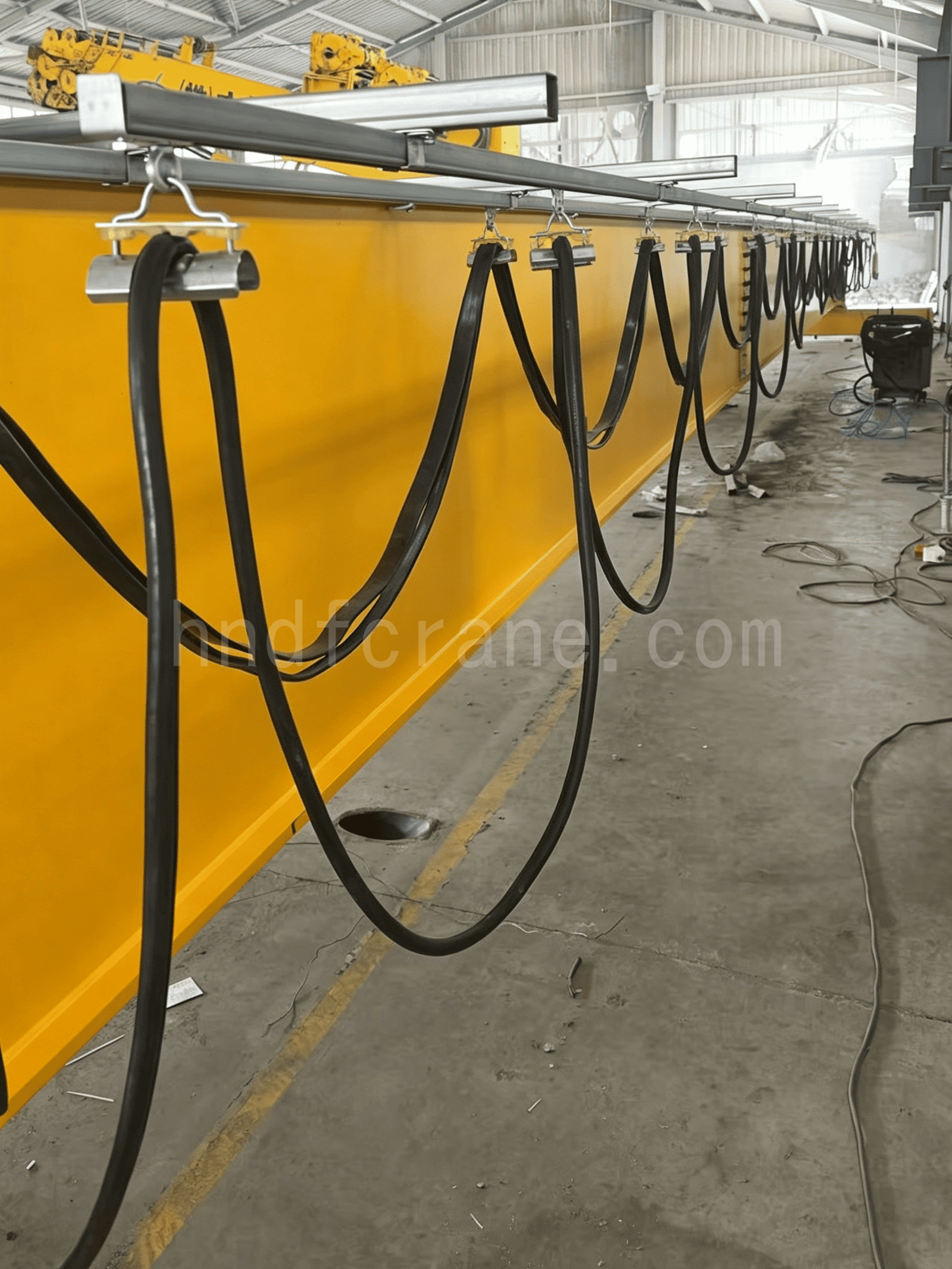
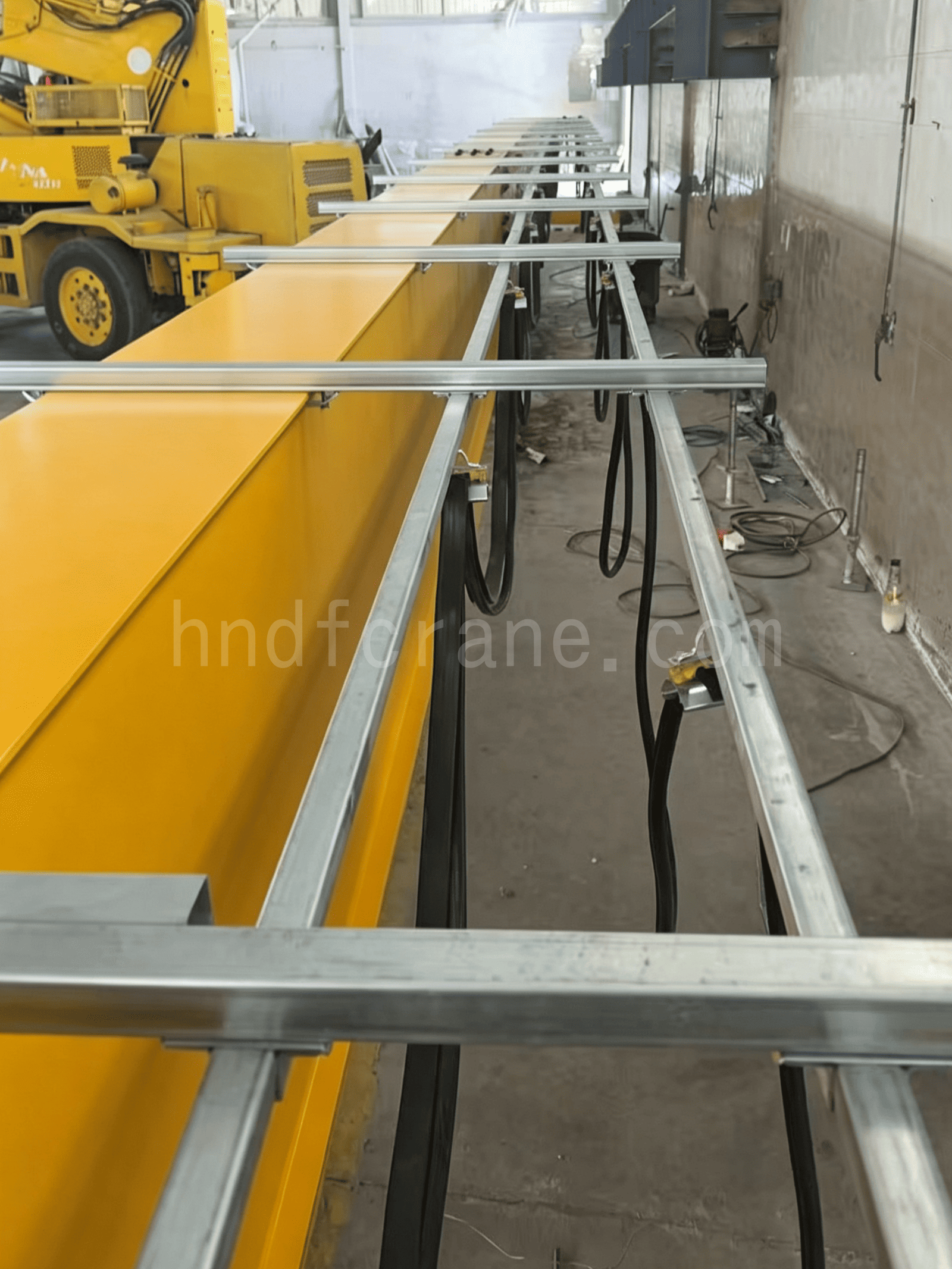
Trolley Travel Cable Installation
The following points should be noted during drag cable installation:
- The cable shall be arranged properly before installation to eliminate twisting and stress.
- The cable shall be arranged in sequence on the end clamp, cable trolley, and towing trolley according to the drawing requirements.
- Adjust the cable length to keep each section of the cable approximately the same length.
- During cable movement, the cable shall remain naturally hanging to avoid stretching or collision.
Electrical Circuit Adjustment
After the electrical components have been set according to the requirements, the electrical circuits shall be inspected and adjusted.
First, conduct a complete inspection of the circuit connection points. Confirm that the wiring is correct and tighten all terminal bolts, then switch on the main power supply of the crane.
When checking the operating sequence of the components in the electrical control cabinet, the main circuit breaker should be disconnected. Turn on the control circuit switch, operate the controller handle step by step, and observe whether the operating sequence of each contactor and relay, as well as all electrical interlocks, comply with the requirements of the electrical schematic diagram. If not, identify the cause and make adjustments.
Check and adjust the setting values of all time relays to ensure they meet the values specified in the factory technical documents.
Manually operate each mechanism limit switch and all safety switches, and check whether they operate flexibly. Confirm that when the protected mechanism reaches its limit position, the power supply can be cut off to provide protection. If any fault is found, identify the cause and eliminate it.
Adjustment of motor rotation direction: Close all switches and operate the controller to jog each mechanism motor separately (energize briefly and then immediately cut off the power). Check whether the motor rotation direction is consistent with the operating direction of the controller; whether the two separately driven motors run in the same direction; and whether the rotation direction matches the direction protected by the limit switches. If not, interchange any two phases of the motor stator wiring to make the rotation direction meet the requirements.
Single Girder Overhead Crane Trial Operation
After the electrical circuits have been fully inspected, adjusted, and confirmed to be correct, close all circuit breakers to connect the main circuits and control circuits of all mechanisms to the power supply.
First, start each mechanism individually under no-load conditions for trial operation and observe whether each mechanism operates normally. Load operation is only allowed after the no-load operation has been confirmed to be normal. During load operation, the load must be gradually increased until reaching the full load. Direct full-load operation is not allowed. For detailed load testing procedures, please refer to “EOT Crane Load Testing: A Step-by-Step Guide”.
After the trial operation is completed and everything operates normally, the electrical equipment of the crane can be put into normal use.
DAFANG CRANE Single Girder Overhead Crane Installation Services
DAFANG CRANE provides comprehensive single girder overhead crane installation services, including on-site installation guidance by experienced engineers, technical support, equipment commissioning, and trial operation. These services help customers complete crane installation safely and efficiently, ensuring stable and reliable crane performance after operation.
Whether you need our engineers to provide on-site installation services or require remote technical support, we can provide flexible and professional solutions according to your project requirements, helping ensure smooth equipment commissioning and operation.

I am Cindy, with 10 years of working experience in the crane industry and accumulated a wealth of professional knowledge. I have chosen the satisfying cranes for 500+ customers. If you have any needs or questions about cranes, please feel free to contact me, I will use my expertise and practical experience to help you solve the problem!
Send Your Inquiry
- Email: sales@hndfcrane.com
- WhatsApp: +86 191 3738 6654
- Telegram: +86 191 3738 6654
- Tel: +86-373-581 8299
- Fax: +86-373-215 7000
- Add: Changnao Industrial District, Xinxiang City, Henan Province, China
 WeChat
- Overhead Cranes
- Double Girder Overhead Cranes
- Single Girder Overhead Cranes
- European Type Single Girder Overhead Cranes
- Explosion Proof Overhead Cranes
- Grab And Magnetic Overhead Cranes
- Monorail Cranes
- Foundry Overhead Cranes
- Workstation Cranes
- Jib Cranes
- Wall Mounted Jib Cranes
- Wall Travelling Jib Cranes
- Free Standing Jib Cranes
- Aluminum Jib Cranes: Lightweight, Smooth Rotating Arm for Easy Lifting
- Balance Jib Cranes: Efficient Light Lifting for Short Distance Mechanical Assembly
- Manual Free Standing Jib Cranes: Efficient Manual Lifting Solutions for Limited Space Operations
- Electric Free Standing Jib Cranes: Fully Electric Solution for High Capacity Fast Lifting
- Articulating Jib Cranes: Precision Lifting with Dual Arm Flexibility
- Gantry Cranes
- Double Girder Gantry Cranes
- Semi Gantry Cranes
- Single Girder Gantry Cranes
- Truss Gantry Cranes
- Container Gantry Cranes
- Adjustable Gantry Cranes
- Portable Gantry Cranes
- European Gantry Cranes
- Industries
- General Manufacturing
- Waste Handling
- Precast
- Power
- Stone
- Papermaking
- Metal Production
- Bridge Construction
- Port Cranes: For Container and Bulk Material Handling
- Overhead Cranes for Petroleum and Gas Industry: Enhance Operational Efficiency
- Marine Cranes for Efficient Cargo Loading on Ships
- Overhead Cranes for the Automotive Industry: Efficient Automation Solutions
- Electric Hoists
- Electric Wire Rope Hoists
- Electric Chain Hoists
- European Type Electric Hoists
- European Electric Chain Hoists: Smooth Operation, Low Noise, and Energy Efficiency
- Manual Lever Hoists: Ideal for Pulling and Lifting Tasks
- Hand Chain Hoists: Manual Lifting for Areas Without Power
- Low Headroom Electric Hoists: Compact Design for Maximum Space Efficiency
- Pneumatic Chain Hoists: Smooth Handling for Industrial Use
- Explosion Proof Manual Chain Hoists: Spark Resistant Copper Alloy Construction for Hazardous Areas
- Explosion Proof Electric Chain Hoists for Hazardous Area Lifting
- Contact Us
- Email: sales@hndfcrane.com
- WhatsApp: +86 191 3738 6654
- Telegram: +86 191 3738 6654
- Tel: +86-373-581 8299
-